Published online in Wiley Online Library (wileyonlinelibrary.com). DOI: 10.1002/uog.12403
ISUOG Practice Guidelines (updated): sonographic screening examination of the fetal heart
Clinical Standards CommitteeIntroduction
This document constitutes a revised and updated version of the previously published ISUOG guidelines for cardiac screening in midgestation1 and reflects current knowledge about prenatal detection of congenital heart disease (CHD). The new ISUOG recommendation that outflow tract views as well as the four-chamber view be added to routine screening is evidence-based and parallels recent guidelines and recommendations from other professional bodies2–5. CHD is a leading cause of infant mortality, with an estimated incidence of about 4–13 per 1000 live births6–8. Between 1950 and 1994, 42% of infant deaths reported to the World Health Organization were attributable to cardiac defects9. Structural cardiac anomalies were also among the abnormalities most frequently missed by prenatal ultrasonography10,11. Prenatal detection of CHD may improve the outcome of fetuses with specific types of cardiac lesions12–16, but prenatal detection rates vary widely17. Some of this variation can be attributed to differences in examiner experience, maternal obesity, transducer frequency, abdominal scars, gestational age, amniotic fluid volume and fetal position18,19. Continuous feedback-based training of healthcare professionals, a low threshold for echocardiography referrals and convenient access to fetal heart specialists are particularly important factors that can improve the effectiveness of a screening program8,20. As one example, the detection rate of major cardiac anomalies doubled after implementation of a 2-year training program at a medical facility in Northern England21. The cardiac screening examination of the fetus is designed to maximize the detection of heart anomalies during a second-trimester scan22. These Guidelines can be used in the evaluation of low-risk fetuses examined as part of routine prenatal care23–25. This approach also helps to identify fetuses at risk for genetic syndromes and provides useful information for patient counseling, obstetric management and multidisciplinary care. Suspected heart anomalies will require more comprehensive evaluation using fetal echocardiography26.
General considerations
Despite the well-documented utility of the four-chamber and outflow tract views, one should be aware of the potential diagnostic pitfalls that can prevent timely detection of CHD27–29. Detection rates can be optimized by performing a thorough screening examination of the heart, recognizing that the four-chamber view is much more than a simple count of cardiac chambers, understanding that some lesions are not discovered until later in pregnancy, and being aware that specific types of abnormalities (e.g. transposition of the great arteries or aortic coarctation) may not be evident from the four-chamber plane alone. Complementing the four-chamber view with the outflow tract views in the cardiac screening examination is therefore an important step to improve detection of CHD. Gestational age The cardiac screening examination is performed optimally between 18 and 22weeks’ menstrual age, although many anatomical structures can still be visualized satisfactorily beyond 22 weeks. Some anomalies may be identified during the late first and early second trimesters of pregnancy, especially when increased nuchal translucency thickness is identified30–35. Screening at 20–22 weeks’ gestation is less likely to require an additional scan for completion of this evaluation, although many patients would prefer to know about major defects at an earlier stage of pregnancy36. Technical factors Gestational age Higher-frequency probes will improve the likelihood of detecting subtle defects, at the expense of reduced acoustic penetration. The highest possible transducer frequency should be used for all examinations, recognizing the trade-off between penetration and resolution. Harmonic imaging may provide improved images, especially for patients with increased maternal abdominal wall thickness during the third trimester of pregnancy37. Imaging parameters Cross-sectional gray-scale imaging is still the basis of a reliable fetal cardiac scan. System settings should emphasize a high frame rate, with increased contrast and high resolution. Low persistence, a single acoustic focal zone and a relatively narrow image field should also be used. Zoom and cine-loop Images should be magnified until the heart fills at least one third to one half of the screen. The cine-loop feature should be used to assist the real-time evaluation of normal cardiac structures, for example, to confirm movement of heart valve leaflets throughout the cardiac cycle. Image magnification and use of cine-loop may help in identifying abnormalities.
Cardiac examination
Considering the time elapsed since the publication of
the initial ISUOG guidelines1, and recent evidence from
the literature, the cardiac screening examination should
now include both the four-chamber and outflow tract
views38–46.
Four-chamber view
The four-chamber view involves careful evaluation of
specific criteria and should not be mistaken for a simple
chamber count. The main elements for examination of
the four chambers are shown in Table 1 and Figures 1
and 2. To assess cardiac situs, it is necessary that fetal
laterality i.e. identification of fetal right and left sides, be determined first, prior to ascertaining that
both stomach and heart are on the left side of the fetus. A normal heart
is usually no larger than one third of the area of the chest.
Some views may reveal a small hypoechogenic rim around
the fetal heart, which can be mistaken for a pericardial
effusion. An isolated finding of this type usually represents
a normal variation47,48.
 The heart is mainly situated on the left side of the
chest and its long axis normally points to the left by
about 45±20◦ (2 SD)49 (Figure 1). Careful attention
should be paid to cardiac axis and position, which can
be evaluated easily even if the four-chamber view is not
visualized satisfactorily50. Situs abnormalities should be
suspected when the fetal heart and/or stomach are not
found on the left side. Abnormal axis increases the risk of
a cardiac malformation, especially involving the outflow
tracts. This finding may also be associated with a chromosomal
anomaly. Abnormal displacement of the heart
from its normal anterior left position can be caused by
a diaphragmatic hernia or space-occupying lesion, such
as cystic adenomatoid malformation of the lung. Position
abnormalities can also be secondary to fetal lung hypoplasia
or agenesis. A shift of the axis to the left may also
occur with fetal gastroschisis and omphalocele.
Normal heart rate and regular rhythm should be confirmed.
The normal rate ranges from 120 to 160 beats per
minute (bpm). Mild bradycardia is observed transiently in
normal second-trimester fetuses. Fixed bradycardia, especially
heart rates that remain below 110 bpm51, requires
timely evaluation by a fetal cardiac specialist for possible
heart block. Repeated heart rate decelerations during the
third trimester can be caused by fetal hypoxia. Occasional
skipped beats are typically not associated with an
increased risk of structural fetal heart disease and are
often benign and resolve spontaneously. However, some
cases may occur with clinically significant dysrhythmias
and are an indication for fetal echocardiography52–54.
Alternatively, reassurance can be provided by more
frequent Doppler auscultation and a targeted scan to
rule out effusions and confirm normal views of the
fetal heart. Mild tachycardia (>160 bpm) can occur
as a normal variant during fetal movement. Persistent
tachycardia (≥180 bpm)55, however, should be evaluated
further for possible fetal hypoxia or more serious
tachydysrhythmias.
Both atrial chambers normally appear similar in size
and the foramen ovale flap should open into the left
atrium. The lower rim of atrial septal tissue, called the
septum primum, should be present. This forms part of the
cardiac ‘crux’, the point where the lower part of the atrial
septum meets the upper part of the ventricular septum
and where the atrioventricular valves insert. Pulmonary
veins can often be seen entering the left atrium and, when
technically feasible, visualization of at least two of these
veins is recommended.

Figure 1: (a) Abdominal situs is ascertained in a transverse view of the fetal abdomen. After determining fetal laterality from position of the fetus in utero, the stomach should be identified on the fetal left side with the descending aorta (D. Aorta) and inferior vena cava (IVC) to the left and right sides of the spine, respectively. A short segment of the umbilical vein (UV) is seen. (b) Cardiac position and axis: the heart is mainly on the left (L) side. The cardiac apex points to the left by 45±20◦ in relation to the anteroposterior axis of the chest. LA, left atrium; LV, left ventricle; R, right; RA, right atrium; RV, right ventricle.
The moderator band, a distinct muscle bundle that
crosses the right ventricular cavity, is seen near the apex
and helps to identify the morphological right ventricle.
The left ventricular apex appears smooth and forms the
apex of the heart. Both ventricles should appear similar
in size and have no evidence of thickened walls.
Although mild ventricular disproportion can occur as
a normal variant in the third trimester of pregnancy,
overt right–left asymmetry in midgestation warrants further
examination56; left-sided obstructive lesions, such as
coarctation of the aorta and evolving hypoplastic left heart
syndrome, are important causes of this disparity57,58.
The ventricular septum should be examined carefully
for cardiac wall defects, from the apex to the crux. Septal
defects may be difficult to detect. The septum is best seen
when the angle of insonation is perpendicular to it. When
the ultrasound beam is directly parallel to the ventricular
wall, a defect may be suspected falsely because of acoustic
‘drop-out’ artifact. Small septal defects (1–2 mm) can be
very difficult to confirm if the ultrasound imaging system
fails to provide a sufficient degree of lateral resolution,
especially if fetal size and position are unfavorable. However,
in most cases these are of limited clinical significance
and may even undergo spontaneous closure in utero59,60.
Two distinct atrioventricular valves (right-sided, tricuspid;
left-sided, mitral) should be seen to open separately
and freely. The septal leaflet of the tricuspid valve is
inserted into the septum closer to the apex when compared
with that of the mitral valve (i.e. normal offset).
Abnormal alignment of the atrioventricular valves can be
a key sonographic finding for cardiac anomalies such as
atrioventricular septal defect.
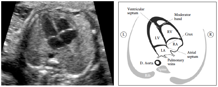
Figure 2: Four-chamber view. The key elements of the normal mid-trimester four-chamber view include heart area no more than one third of chest area, right- and left-sided structures approximately equal (chamber size and wall thickness), a patent foramen ovale with its valve in the left atrium, an intact cardiac ‘crux’ with normal offset of the two atrioventricular valves and intact ventricular septum. The morphological right ventricle (RV) is identified by the presence of the moderator band and tricuspid valve, this valve inserting more apically in the septum than does the mitral valve (normal offset). D. Aorta, descending aorta; L, left; LA, left atrium; LV, left ventricle; R, right; RA, right atrium.
Outflow tract views
Views of the left and right ventricular outflow tracts
(LVOT and RVOT) are considered an integral part of
the fetal cardiac screening examination. It is important
to ascertain normality of the two vessels, including their
connection to the appropriate ventricles, their relative
size and position and adequate opening of the arterial
valves. It is recommended that in cases when this cannot
be confirmed, further evaluation be carried out.
At the very least, examination of the outflow tracts
requires that the great vessels are approximately equal
in size and cross each other at right angles from their
origins as they exit from the respective ventricles (normal
‘cross-over’, Appendix S1, Panel 1). A large obstetric
ultrasound survey of over 18 000 fetuses61 examined the
standardized practice of incorporating the four-chamber
view and, when technically feasible, evaluation of the
outflow tracts, into the routine 30-min examination.
Most (93%) examinations that included an adequate
four-chamber view were also associated with satisfactory
evaluation of the outflow tracts. Non-visualization rates
were: 4.2% for the LVOT, 1.6% for the RVOT and 1.3%
for both outflow tracts.
Additional cross-sectional views show different aspects
of the great vessels and surrounding structures, but are
part of a continuous sweep starting from the RVOT and
include the three-vessel (3V) view and the three vessels
and trachea (3VT) view (Appendix S1, Panel 2). In a study
involving nearly 3000 low-risk pregnancies examined by
one operator, the 3V view and the 3VT view were added to
the standard four-chamber view as part of routine screening.
The average time to obtain the cardiac views was
just over 2 min (135 s; SD, 20 s) but in approximately one
third of cases the cardiac examination was postponed by
15–20 min due to unfavorable fetal lie (anterior spine)46.
The evaluation of outflow tracts increases the detection
rates for major cardiac malformations above those
achievable by the four-chamber view alone20,40,42,62,63.
The inclusion of outflow tract views is more likely to
identify conotruncal anomalies such as tetralogy of Fallot,
transposition of the great arteries, double outlet right
ventricle and truncus arteriosus43–46,64–69.
Sonographic technique
Performing a transverse sweep (sweep technique) with
cephalad movement of the transducer from the fetal
abdomen (at the level of the standard abdominal circumference)
through the four-chamber view and towards the
upper mediastinum offers a systematic way of assessing
the fetal heart and provides the various views through
which normality of the outflow tracts views can be ascertained:
LVOT, RVOT, 3V and 3VT views70, (Figure 3).
In the ideal exam, all outflow tract views can be obtained
with relative ease. However, it may not be technically
feasible to demonstrate all of these in every patient
during routine screening. Hence, being familiar with all is
desirable.
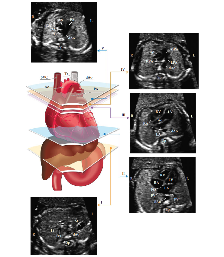
Figure 3: The five axial views for optimal fetal heart screening. The color image shows the trachea (Tr), heart and great vessels, liver and stomach, with the five planes of insonation indicated by polygons corresponding to the gray-scale images, as indicated. (I) Most caudal plane, showing the fetal stomach (St), cross-section of the descending aorta (dAo), spine (Sp) and liver (Li). (II) Four-chamber view of the fetal heart, showing the right and left ventricles (RV, LV) and atria (RA, LA), foramen ovale (FO) and pulmonary veins (PV) to the right and left of the dAo. (III) Left ventricular outflow tract view, showing the aortic root (Ao), LV, RV, LA and RA and a cross-section of the dAo. (IV) Slightly more cephalad view (right ventricular outflow tract view) showing the main pulmonary artery (MPA) and the bifurcation into the right (RPA) and left (LPA) pulmonary arteries and cross-sections of the ascending aorta (Ao) and dAo aorta. (V) Three vessels and trachea view showing the superior vena cava (SVC), pulmonary artery (PA), ductus arteriosus (DA), transverse aortic arch (from proximal Ao to dAo) and trachea (Tr). IVC, inferior vena cava; L, left; R, right. Modified with permission from Yagel et al.70.
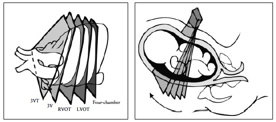
Figure 4: Fetal heart scanning technique. The four-chamber view is obtained through an axial scanning plane across the fetal chest. Cephalad tilting of the transducer from the four-chamber view towards the fetal head gives the outflow tract views sequentially: left ventricular outflow tract (LVOT), right ventricular outflow tract (RVOT), three-vessel (3V) and three vessels and trachea (3VT) views.
The LVOT and RVOT views can be obtained by sliding
(or angling) the transducer towards the fetal head (sweep
technique) (Figure 4), starting from a four-chamber view
to obtain the normal cross-over of the aorta and main
pulmonary artery at their origin. Details of the pulmonary
artery bifurcation can also be seen (Appendix S1, Panels
1 and 2). Alternatively, a variation in the method for
evaluating the outflow tracts in the fetus has also been
described: the rotational technique41 (Appendix S2, Panel
1). From a four-chamber view of the heart, the transducer
is first rotated towards the fetal right shoulder. This technique,
more easily performed when the interventricular
septum is perpendicular to the ultrasound beam, may
require slightly more manual skills but optimizes visualization
of the LVOT, especially the septoaortic continuity.
It also allows visualization of the whole ascending aorta,
as opposed to only its proximal part as with the sweep
technique. With both techniques, once the LVOT view
is obtained, the transducer is angled cephalad until the
pulmonary artery is observed with a direction almost
perpendicular to that of the aorta.
Additional views of the aorta and pulmonary artery
can be obtained by further sliding or tilting the transducer
towards the fetal head from the RVOT. These views correspond
to the 3V view and the 3VT view, in which the
relationship of the two arteries with the superior vena
cava and trachea is shown. The ductal arch as well as
the transverse aortic arch can also be imaged at this
level64–67.
Left ventricular outflow tract (LVOT) view. The LVOT
view confirms the presence of a great vessel originating
from the morphological left ventricle (Figure 5). Continuity
should be documented between the ventricular septum
and the anterior wall of this vessel, the aorta. The aortic
valve moves freely and should not be thickened. It is
possible to trace the aorta into its arch, from which three
arteries originate into the neck. However, identification
of these aortic arch vessels is not considered as a routine
part of the cardiac examination. The LVOT view helps to
identify outlet ventricular septal defects and conotruncal
abnormalities that are not seen during examination of the
four-chamber view alone.
Right ventricular outflow tract (RVOT) view. The
RVOT view confirms the presence of a great vessel originating
from the morphological right ventricle (Figure 6):
the pulmonary artery normally arises from this ventricle
and courses towards the left of the more posterior ascending
aorta. It is usually slightly larger than the aortic root
during fetal life and crosses the ascending aorta at almost
a right angle just above its origin. At this level, as seen in
Figure 6, the superior vena cava is often seen to the right
of the aorta. This view is similar to the 3V view, described
by Yoo et al.64.
The pulmonary valve moves freely and should not be
thickened. The vessel originating from the RVOT can be
confirmed as the pulmonary artery only if it branches
after a short course. The take-off of the right branch
of the pulmonary artery comes first and the left branch
subsequently. This division cannot always be seen owing
to fetal position. The normal pulmonary artery continues
distally towards the left side and into the ductus arteriosus
that connects to the descending aorta (Figure 6 and
Appendix S1).
Three-vessel (3V) view and three vessels and trachea
(3VT) view. Visualization of the 3V view and 3VT view is
desirable and should be attempted as part of the routine
cardiac screening examination, although it may not be
technically feasible to obtain them in all patients.
These two standard ultrasound planes define three vascular
structures, and their relationships with each other
and with the airways (trachea). Yoo et al.64 described
the 3V view to evaluate the pulmonary artery, ascending
aorta and superior vena cava, and their relative sizes and
relationships (Figure 7). Briefly, an assessment of vessel
number, size, alignment and arrangement needs to be
made. From left to right, the vessels are the pulmonary
artery, the aorta and the superior vena cava. The pulmonary
artery is the most anterior vessel and the superior
vena cava is the most posterior. Their relative diameters
decrease from left to right, with the pulmonary artery
being larger than the aorta, and the aorta larger than the
superior vena cava. Typically, certain abnormalities associated
with a normal four-chamber view, such as complete
transposition of the great arteries, tetralogy of Fallot and
pulmonary atresia with a ventricular septal defect, are
likely to have an abnormal 3V view. Yagel et al.67 subsequently
described the 3VT view, which is a more cephalad
image, in which the transverse aortic arch is better visualized
(‘aortic arch view’) and its relationship with the
trachea emphasized. The trachea is usually identified as a
hyperechogenic ring surrounding a small fluid-filled space.
Both the ductal and aortic arches are positioned to the left
of the trachea and form a ‘V’ shape as they both join the
descending aorta (Figure 8). The aortic arch is the most
cranial of the two arches, therefore to image both arches
simultaneously may require some transducer adjustments,
away from the plane that is parallel to the four-chamber
view. The 3VT view is likely to enable detection of lesions
such as coarctation of the aorta, right aortic arch, double
aortic arch and vascular rings.

Figure 5:
Left ventricular outflow tract (LVOT) view. This view shows a vessel connected to the left ventricle (LV). It is important to
demonstrate continuity between the interventricular septum and the anterior wall of this vessel, which in the normal heart corresponds to
the aorta. The aortic valve should not be thickened and should be shown to open freely. The aortic valve is closed in (a) and open in (b).
D. Aorta, descending aorta; L, left; LA, left atrium; R, right; RA, right atrium; RV, right ventricle.
Color flow doppler
Sonography overview
The purpose of performing an ultrasound examination
in a woman with suspected endometriosis is to try to
explain underlying symptoms, map the disease location
and assess the severity of disease prior to medical
therapy or surgical intervention. Various ultrasound
approaches have been published, but to date none has
been externally validated16,17. We propose four basic
sonographic steps when examining women with suspected
or known endometriosis, as shown in Figure 1. Note that
these steps can be adopted in this or any order as long
as ALL four steps are performed to confirm/exclude the
different forms of endometriosis.
Using TVS as the first-line imaging tool, the operator
should examine the uterus and the adnexa. The mobility
of the uterus should be evaluated: normal, reduced
or fixed (‘question mark sign’)18. Sonographic signs
of adenomyosis should be searched for and described
using the terms and definitions published in the
Morphological Uterus Sonographic Assessment consensus
opinion19.
The presence or absence of endometriomas (Figure S1a),
their size, measured systematically in three orthogonal
planes (see ‘Measurement of lesions’, below), the number
of endometriomas and their ultrasound appearance
should be noted20. The sonographic characteristics of any
endometrioma should be described using the International
Ovarian Tumor Analysis terminology21. An atypical
endometrioma (Figure S1b) is defined as a unilocular-solid
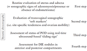
Figure 1 Four basic sonographic steps for examining women with
clinical suspicion of deep infiltrating endometriosis (DIE) or known
endometriosis. All steps should be performed, but not necessarily in
this order. Note, bladder should contain small amount of urine.
Dynamic ultrasonography is when the operator performing the
ultrasound examination assesses both the pelvic organs and their
mobility in real-time. POD, pouch of Douglas.
mass with ground glass echogenicity with a papillary
projection, a color score of 1 or 2 and no flow inside the
papillary projection20.
Ovarian endometriomas are associated frequently
with other endometriotic lesions, such as adhesions
and DIE22,23. The ‘kissing’ ovaries sign (Figure S2)
suggests that there are severe pelvic adhesions; bowel
and Fallopian tube endometriosis are significantly more
frequent in women with kissing ovaries vs those without
kissing ovaries: 18.5% vs 2.5% and 92.6% vs 33%,
respectively24.
Endometriomas may undergo decidualization in pregnancy,
in which case they can be confused with an ovarian
malignancy on ultrasound examination (Figure S3)25.
Simultaneous presence of other endometriotic lesions
may facilitate a correct diagnosis of endometrioma in
pregnancy and minimize the risk of unnecessary surgery.
The second step is to search for sonographic ‘soft
markers’, i.e. site-specific tenderness (SST) and fixed
ovaries. The presence of soft markers increases the likelihood
of superficial endometriosis and adhesions26,27. By
applying pressure between the uterus and ovary, one can
assess if the ovary is fixed to the uterus medially, to the
pelvic side wall laterally or to the USLs. The presence of
adhesions can also be suspected if, on palpation with the
probe and/or abdominal palpation with the free hand,
the ovaries or the uterus appear to be fixed to adjacent
structures (broad ligament, POD, bladder, rectum and/or
parietal peritoneum). If there is pelvic fluid, fine strands
of tissue (adhesions) may be seen between the ovary
(with or without endometrioma) and the uterus or the
peritoneum of the POD27–30.
If there are endometriomas or pelvic endometriosis, the
Fallopian tubes are frequently involved in the disease
process. Adhesions may distort the normal Fallopian
tubal course and occlusion of the Fallopian tube(s) by
endometriotic foci or distal tubular adhesions may also
occur. As a consequence, a sactosalpinx may develop. For
these reasons, hydrosalpinx/hematosalpinx and peritoneal
cysts should be searched for and reported.
The third step is to assess the status of the POD
using the real-time TVS-based ‘sliding sign’. In order
to assess the sliding sign when the uterus is anteverted
(Figure 2a), gentle pressure is placed against the cervix
using the transvaginal probe, to establish whether the
anterior rectum glides freely across the posterior aspect
of the cervix (retrocervical region) and posterior vaginal
wall. If the anterior rectal wall does so, the ‘sliding sign’ is
considered positive for this location (Videoclip S1a). The
examiner then places one hand over the woman’s lower
anterior abdominal wall in order to ballot the uterus
between the palpating hand and the transvaginal probe
(which is held in the other hand), to assess whether the
anterior bowel glides freely over the posterior aspect of the
upper uterus/fundus. If it does so, the sliding sign is also
considered positive in this region (Videoclip S1b). When
the sliding sign is found to be positive in both of these
anatomical regions (retrocervix and posterior uterine
fundus), the POD is recorded as being not obliterated.
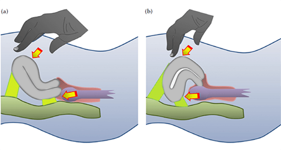
Figure 2: Schematic drawings demonstrating how to elicit the ‘sliding sign’ in an anteverted uterus (a) and a retroverted uterus (b).
If on TVS it is demonstrated that either the anterior rectal wall or the anterior sigmoid wall does not glide smoothly over the retrocervix or the posterior uterine fundus, respectively, i.e. at least one of the locations has a negative sliding sign, then the POD is recorded as obliterated31,32. Demonstrating and describing the real-time ultrasound-based sliding sign in a retroverted uterus is different (Figure 2b). Gentle pressure is placed against the posterior upper uterine fundus with the transvaginal probe, to establish whether the anterior rectum glides freely across the posterior upper uterine fundus. If the anterior rectum does so, the sliding sign is considered to be positive for this location (Videoclip S2a). The examiner then places one hand over the woman’s lower anterior abdominal wall in order to ballot the uterus between the palpating hand and transvaginal probe (which is held in the other hand), to assess whether the anterior sigmoid glides freely over the anterior lower uterine segment. If it does so, the sliding sign is also considered to be positive in this region (Videoclip S2b). As long as the sliding sign is found to be positive in both of these anatomical regions (i.e. the posterior uterine fundus and the anterior lower uterine segment), the POD is recorded as non-obliterated33. The fourth step is to search for DIE nodules in the anterior and posterior compartments. To assess the anterior compartment, the transducer is positioned in the anterior fornix of the vagina. If bladder endometriosis is suspected on the basis of symptoms, patients should be asked not to empty their bladder completely before the ultrasound examination. A slightly filled bladder facilitates evaluation of the walls of the bladder and detection and description of endometriotic nodules. Finally, the transducer is positioned in the posterior fornix of the vagina and slowly withdrawn through the vagina to allow visualization of the posterior compartment. Some authors advocate the use of bowel preparation on the evening before the pelvic scan and the use of a rectal enema within an hour before the ultrasound examination to eliminate fecal residue and gas in the rectosigmoid34–37. However, this is not mandatory, and there are no published prospective studies comparing TVS with and without bowel preparation for the diagnosis of bowel DIE. In a recent meta-analysis, TVS, either with or without bowel preparation, was found to be an accurate predictor of rectosigmoid DIE8.
COMPARTMENTAL EVALUATION
Anterior compartment
The anterior compartment includes the following anatomical locations: urinary bladder, uterovesical
region and
ureters.
Urinary bladder
Bladder DIE occurs more frequently in the bladder
base and bladder dome than in the extra-abdominal
bladder (Videoclip S3)38. The bladder is best scanned
if it contains a small amount of urine because this
reduces false-negative findings. Although Savelli et al.38
described two zones (bladder base and dome), we propose
dividing the bladder ultrasound assessment into four
zones (Figure 3): (i) the trigonal zone, which lies within
3 cm of the urethral opening, is a smooth triangular
region delimited by the two ureteral orifices and the
internal urethral orifice (Figure S4a); (ii) the bladder base,
which faces backward and downward and lies adjacent
to both the vagina and the supravaginal cervix (Figure
S4b); (iii) the bladder dome, which lies superior to the
base and is intra-abdominal (Figure S4c); and (iv) the
extra-abdominal bladder (Figure S4d). Figure S5 and
Videoclip S3 demonstrate the most frequent location of
endometriotic bladder nodules, i.e. the bladder base.
On two-dimensional (2D) ultrasound the appearance
of DIE in the anterior compartment can be varied,
including hypoechoic linear or spherical lesions, with
or without regular contours involving the muscularis
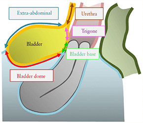
Figure 3Schematic drawing illustrating the four bladder zones:
trigone, bladder base, bladder dome and extra-abdominal bladder.
The demarcation point between the base and the dome of the
bladder is the uterovesical pouch.
(most common) or (sub)mucosa of the bladder6,38–43. The dimensions of the bladder nodule should be measured in three orthogonal planes. Bladder DIE is diagnosed only if the muscularis of the bladder wall is affected; lesions involving only the serosa represent superficial disease.
Uterovesical region
Obliteration of the uterovesical region can be evaluated using the sliding sign, i.e. the transvaginal probe is placed in the anterior fornix and the uterus is balloted between the probe and one hand of the operator placed over the suprapubic region. If the posterior bladder slides freely over the anterior uterine wall, then the sliding sign is positive and the uterovesical region is classified as non-obliterated (Videoclip S4). If the bladder does not slide freely over the anterior uterine wall, then the sliding sign is negative and the uterovesical region is classified as obliterated44 (Figure S6). Adhesions in the anterior pelvic compartment are present in nearly one third of women with a previous Cesarean section and are not necessarily a sign of pelvic endometriosis44.
Ureters
The distal ureters should be examined routinely using the transvaginal probe. The ureters can be found by identifying the urethra in the sagittal plane and moving the probe towards the lateral pelvic wall. The intravesical segment of the ureter is identified and its course followed to where it leaves the bladder and then further, to the pelvic side wall and up to the level of the bifurcation of the common iliac vessels. It is helpful to wait for peristalsis to occur as this confirms ureteric patency. Ureters typically appear as long tubular hypoechoic structures, with a thick hyperechoic mantle, extending from the lateral aspect of the bladder base towards the common iliac vessels. Dilatation of the ureter due to endometriosis is caused by stricture (from either extrinsic compression or intrinsic infiltration) and the distance from the distal ureteric orifice to the stricture should be measured (Figure S7)35,45,46. Thorough evaluation of the ureter at the time of surgery is important in all cases in which ureteral involvement is suspected. In all women with DIE, a transabdominal scan of the kidney to search for ureteral stenosis is necessary, because the prevalence of endometriotic lesions in the urinary tract may be underestimated and women with DIE involving the ureter may be asymptomatic47–51. The degree of hydronephrosis should be assessed and graded using generally accepted ultrasound criteria52. Women with evidence of hydronephrosis should be referred for urgent stenting of a stenosed ureter to prevent further loss of renal function.
Posterior compartment
According to Chapron et al.53, the most common sites of DIE in the posterior compartment are: USLs, posterior vaginal fornix, anterior rectum/anterior rectosigmoid junction and sigmoid colon. Sonographic assessment of the posterior compartment should aim at identifying the number, size and anatomical location of DIE nodules affecting these structures.On TVS, posterior compartment DIE lesions appear as hypoechoic thickening of the wall of the bowel or vagina, or as hypoechoic solid nodules which may vary in size and have smooth or irregular contours54.
Rectovaginal septum
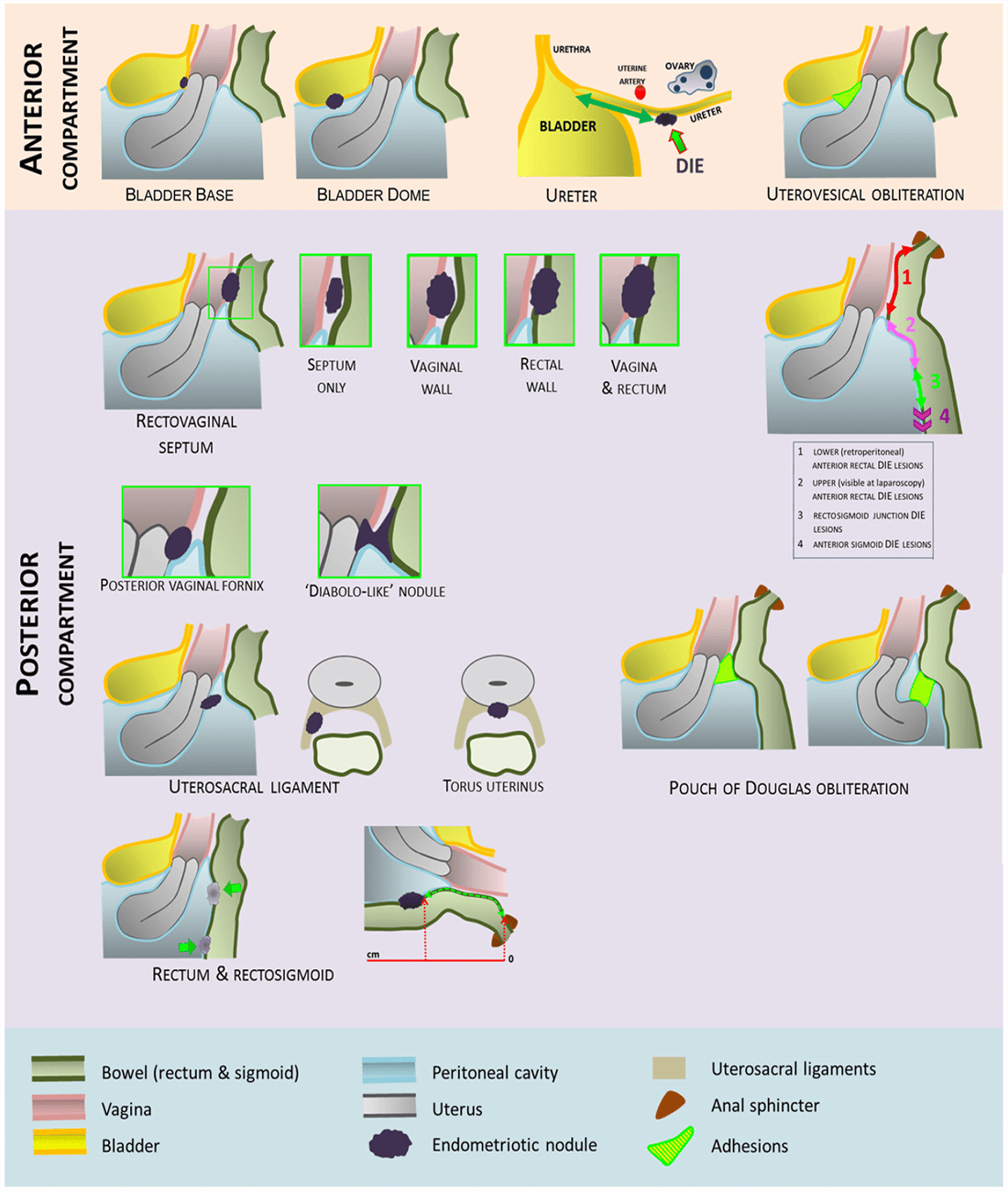
Some studies have defined the TVS diagnosis of DIE in the RVS as absence of the normal appearance of the hyperechoic layer between the vagina and rectum due to the presence of a DIE nodule55. Other researchers have used the terms ‘RVS DIE’ and ‘rectovaginal DIE (RV DIE)’ interchangeably to describe DIE in the RVS55,56. The RVS is an individual anatomical structure with a specific location, whereas RV DIE describes DIE located in the rectovaginal area. The rectovaginal area includes the vagina, the rectum and the RVS. Furthermore, there is inconsistency in the definition of RV DIE in the literature. RV DIE has been described as endometriotic lesions which infiltrate both the rectum and the posterior vaginal fornix with possible extension into the RVS55. Others have used the term ‘rectovaginal endometriosis’ to describe nodules which primarily infiltrate the RVS with possible extension into the vagina and/or rectum. Isolated RVS endometriosis is uncommon. We propose that involvement of the RVS should be suspected when a DIE nodule is seen on TVS in the rectovaginal space below the line passing along the lower border of the posterior lip of the cervix (under the peritoneum)39 (Figure 4). Isolated RVS DIE is rare (Figure 5); RVS DIE is usually an extension of posterior vaginal wall (Figure 6), anterior rectal wall (Figure 7) or both posterior vaginal wall and anterior rectal wall involvement57 (Figure 8). The use of sonovaginography improves the detection of posterior vaginal and RVS
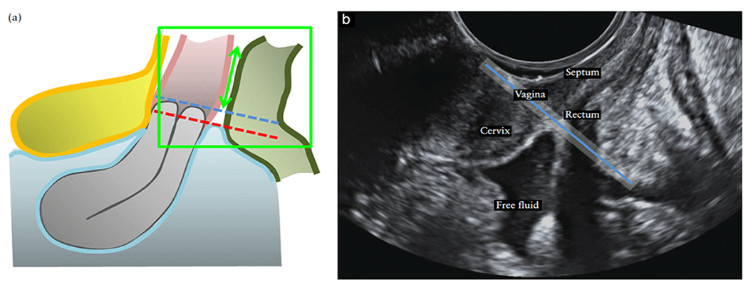
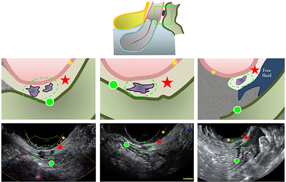
 ). The green ellipses
encircle the endometriotic nodules in the RVS.
  , bowel wall;
 , vaginal wall.

 ). The green ellipses
encircle the endometriotic nodules in the RVS.
  , bowel wall;
 , vaginal wall.

 ).
).  , bowel wall;
 , vaginal wall.

 ) deep infiltrating endometriosis with extension
into both anterior rectal wall and posterior vaginal wall.
  , bowel wall;
  , vaginal wall.
DIE54,58. The dimensions of the RVS DIE nodule should be recorded in three orthogonal planes and the distance between the lower margin of the lesion and the anal verge should be measured. This should be done whether the DIE is only in the vagina or only in the rectum, or involves the vagina, RVS and rectum. Low RVS lesions, when managed surgically, are associated with severe complications, including fistulae56,59–61.
Vaginal wall
We propose that involvement of the posterior vaginal fornix and/or lateral vaginal fornix should be suspected when a DIE nodule is seen on TVS in the rectovaginal space below the line passing along the caudal end of the peritoneum of the lower margin of the rectouterine peritoneal pouch (cul-de-sac of Douglas) and above the line passing along the lower border of the posterior lip of the cervix (under the peritoneum) (seen in Figure 4). Posterior vaginal fornix or forniceal endometriosis is suspected if the posterior vaginal fornix is thickened or if a discrete nodule is found in the hypoechoic layer of the vaginal wall (Figure S8a). The hypoechoic nodule may be homogeneous or inhomogeneous with or without large cystic areas (Figure S8a) and there may or may not be cystic areas surrounding the nodule6,39,41,42. Figure S8b is an ultrasound image demonstrating posterior vaginal fornix DIE. The dimensions of the vaginal wallDIE nodule should be measured in three orthogonal planes. Rectovaginal nodules (‘diabolo’-like nodules) Hourglass-shaped or ‘diabolo’-like nodules occur when DIE lesions in the posterior vaginal fornix extend into
the anterior rectal wall62 (Figure S9a). On ultrasound, the part of the DIE lesion situated in the anterior rectal wall is the same size as the part situated in the posterior vaginal fornix (Figure S9b). There is a small but easily visualized continuum between these two parts of the lesion. These lesions are located below the peritoneum of the POD and are usually large (3 cm on average)63.
Uterosacral ligaments
Normal USLs are usually not visible on ultrasound (Figure S10a). USLDIE lesions can be seen in the mid-sagittal view of the uterus (Figure S10b). However, these are best seen by placing the transvaginal probe in the posterior vaginal fornix in the midline in the sagittal plane and then sweeping the probe inferolaterally to the cervix. USLs are considered to be affected by DIE when a hypoechoic thickening with regular or irregular margins is seen within the peritoneal fat surrounding the USLs. The lesionmay be isolated or may be part of a larger nodule extending into the vagina or into other surrounding structures. The thickness of a ‘thickened’ USL can be measured in the transverse plane at the insertion of the ligament on the cervix provided that the ligament can be distinguished clearly from adjacent structures (Figure S10c). In some cases the DIE lesion involving the USL is located at the torus uterinus (Figure S10d). If so, it is seen as a central thickening of the retrocervical area64. The dimensions of the USL DIE nodule should be recorded in three orthogonal planes.
Rectum, rectosigmoid junction and sigmoid
Bowel DIE classically involves the anterior rectum,
rectosigmoid junction and/or sigmoid colon, all of which
can be visualized using TVS. Figure S11a demonstrates
a schematic drawing of a DIE lesion within the upper
anterior rectum. Bowel DIE can take the form of an
isolated lesion or can be multifocal (multiple lesions
affecting the same segment) and/or multicentric (multiple
lesions affecting several bowel segments, i.e. small bowel,
large bowel, cecum, ileocecal junction and/or appendix)65.
Although TVS can be used to visualize multifocal rectal
DIE (Figure S11b), there are no published data assessing
its performance. Computed tomographic colonography
and magnetic resonance imaging (MRI) can be used
to diagnose both multifocal and multicentric bowel
endometriosis65.
Histologically, bowel endometriosis is defined as the
presence of endometrial glands and stroma in the bowel
wall, reaching at least the muscularis propria66, where
this invariably induces smooth-muscle hyperplasia and
fibrosis. This results in thickening of the bowel wall
and some narrowing of the bowel lumen. Normal rectal
wall layers can be visualized on TVS: the anterior
rectal serosa is seen as a thin hyperechoic line; the
muscularis propria is hypoechoic, with the longitudinal
smooth muscle (outer) and circular smooth muscle (inner)
separated by a faint thin hyperechoic line; the submucosa
is hyperechogenic; and the mucosa is hypoechoic37,67
(Figure S12a). Bowel DIE usually appears on TVS as a
thickening of the hypoechoic muscularis propria or as
hypoechoic nodules, with or without hyperechoic foci
(Figure S12b) with blurred margins. The morphological
type of bowel lesion should be described according to
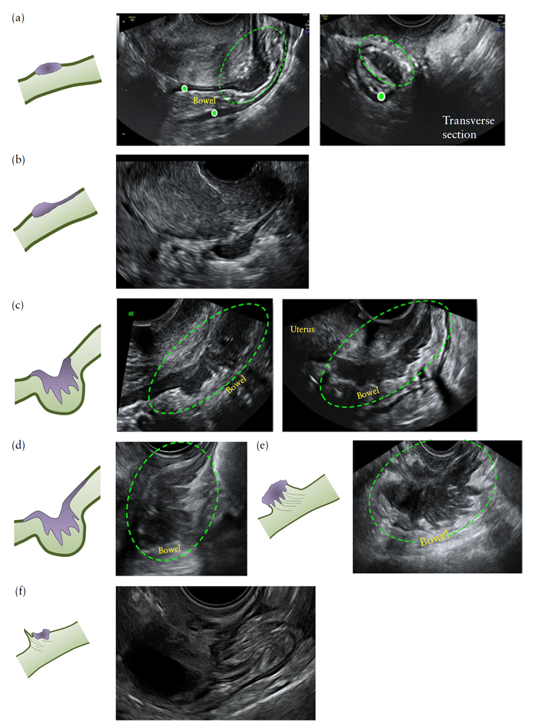
Figure 9. Sonographically, bowel lesions are hypoechoic
and in some cases a thinner section or a ‘tail’ is noted at
one end, resembling a ‘comet’68 (Figure 9b). The normal
appearance of the muscularis propria of the rectum
or rectosigmoid is replaced by a nodule of abnormal
tissue with possible retraction and adhesions, resulting
in the so-called ‘Indian headdress’ or ‘moose antler’ sign
(Figure 9c,e,f)42; the size of these lesions can vary.
We propose that bowel DIE lesions noted on TVS
be described according to the segment of the rectum or
sigmoid colon in which they occur, with DIE lesions
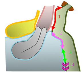
Figure 10Schematic drawing demonstrating distinction at
ultrasound between segments of the rectum and sigmoid colon for
specifying location of deep infiltrating endometriotic lesions: lower
(or retroperitoneal) anterior rectum (1); upper (visible at
laparoscopy) anterior rectum (2); rectosigmoid junction (3); and
anterior sigmoid (4).
located above the level of the insertion of the USLs on the cervix being denoted as lower (retroperitoneal) anterior rectal DIE lesions, those above this level being denoted as upper (visible at laparoscopy) anterior rectal DIE lesions, those at the level of the uterine fundus being denoted as rectosigmoid junction DIE lesions and those above the level of the uterine fundus being denoted as anterior sigmoid DIE lesions (Figure 10). The dimensions of the rectal and/or rectosigmoid DIE nodules should be recorded in three orthogonal planes and the distance between the lower margin of the most caudal lesion and the anal verge should be measured using TVS. Because bowel DIEmay affect the bowel simultaneously at different sites, other bowel lesions should be looked for carefully when there is a DIE lesion affecting the rectum (Figure S12b) or rectosigmoid. Preliminary data showed that rectal DIE lesions may be associated with a second intestinal lesion in 54.6% of cases34. Ultrasound diagnosis of POD obliteration31,32 has been explained extensively earlier in this article. The obliteration can be graded as partial or complete depending on whether one side (left or right) or both sides, respectively, demonstrate a negative sliding sign. Furthermore, an experienced operator can identify the level of POD obliteration, i.e. specifying, in an anteverted uterus, whether it is at the retrocervical level (lower third of the uterus), mid-posterior uterus (middle third) and/or posterior uterine fundus (upper third)69 and, in a retroverted uterus, whether it is at the posterior uterine fundus, mid-anterior uterus and/or lower anterior uterine wall33(Figure S13).
MEASUREMENT OF LESIONS
We propose that each endometrioma and DIE lesion should be measured systematically in three orthogonal

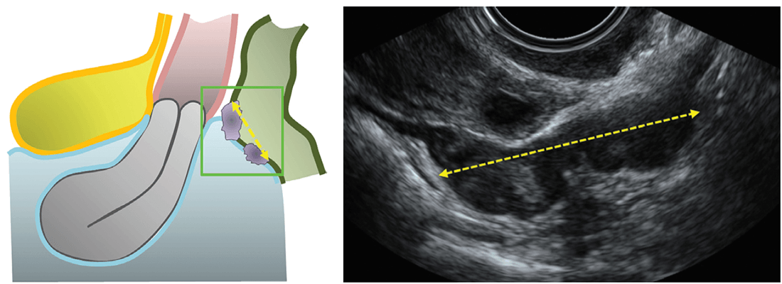
planes, to obtain the length (mid-sagittal measurement), thickness (anteroposterior measurement) and transverse diameter (Figure 11). This approach of measuring in three planes applies to DIE lesions located in the bladder, RVS, vagina, USLs, anterior rectum and rectosigmoid. Additionally, in cases of endometriosis in the ureters, it is important to measure the distance between the distal ureteric orifice and a DIE lesion which causes a ureteric stricture; the stricture can be caused by either extrinsic compression or intrinsic infiltration. Once the stricture is identified along the longitudinal course of the ureter, one caliper should be placed at this level and the other at the distal ureteric orifice for measurement (Figure S7). In cases of multifocal bowel DIE lesions the total mid-sagittal length of the bowel segment involved, from caudal to cephalic aspect, should be measured (Figure 12). It is important to be aware that the retraction within rectosigmoid DIE lesions can result in an overestimation of the true thickness of the lesion and an underestimation of the true length of the lesion (Figure S14). This has been described as the ‘mushroom cap’ sign on MRI and can also be noted on TVS70. In cases of DIE lesions in the bowel or RVS, it is important to measure the distance between the anal verge and the lesion (Figure S15). It is possible to measure the distance from the anus to the bowel lesion using transrectal sonography. By inserting the probe into the anus and positioning the tip of the probe up against the endometriotic lesion71, one’s finger can be kept on the probe at the level of the anus and a ruler used to measure the distance from the finger on the probe to the tip of the probe when the probe has been withdrawn. TVS can also be used to approximate the distance from the anal verge to the lower margin of the bowel lesion. If there are multifocal bowel lesions, then the distance between the anal verge and the most caudal bowel lesion is measured. Figure 13 gives an overview of anterior and posterior compartmental locations for deep infiltrating endometriosis.
OTHER ULTRASOUND TECHNIQUES
Color Doppler
Although well established in the evaluation of endometrioma20, no prospective data have been reported for the role of color Doppler in the evaluation of DIE. Usually, endometriotic lesions in the rectosigmoid are poorly vascularized. Color Doppler is useful in the differential diagnosis between DIE in the bowel and rectal
cancer (Figure S16) and we propose that color Doppler be used as an adjunct modality in the assessment of DIE lesions of the bowel.
Tenderness-guided ultrasound examination
Tenderness-guided ultrasound examination is performed with or without an acoustic window between the transvaginal probe and the surrounding vaginal structures, coupled with an ‘active’ role of the patient, who indicates the site of any tenderness experienced during the examination27,41.
Rectal water contrast transvaginal ultrasound
Rectal water contrast TVS requires injection, under ultrasound guidance, of saline through a catheter into the rectum; the procedure is well tolerated36,72 and allows estimation of the degree of stenosis of the bowel lumen73 (Figure S17).
Sonovaginography with saline or gel
Saline contrast sonovaginography combines TVS with injection of saline into the vagina74. A transvaginal probe is used with, at its base, a purpose-designed hydraulic ring that inflates with approximately 40mL saline solution to prevent escape of the 60–120mL saline that is injected into the vagina using a Foley catheter58. The solution creates an acoustic window between the transvaginal probe and the structures surrounding the vagina and exerts pressure that distends the vaginal walls. This permits more complete visualization of the vaginal walls and anterior/ posterior vaginal fornices. In order to perform gel contrast sonovaginography, 20–50mL ultrasound gel is inserted into the posterior vaginal fornix, using a 20-mL plastic syringe, before insertion of the transvaginal probe35,57. The gel creates an acoustic window, allowing a ‘stand-off’ view of the structures of the posterior compartment (Figure S18). The gel must be loaded carefully into the syringe, ensuring there are no or only minimal air bubbles in the gel. The syringe is filled completely, so that the plunger comes in direct contact with the gel, reducing the possibility of air pockets when instilling the gel into the vagina. Great care is taken to ensure that the syringe is inserted sufficiently far into the vagina that the gel fills the posterior fornix completely. In published reports, no woman required any refilling of the posterior fornix with gel35,57.
Transrectal sonography using transvaginal probe
Transrectal sonography61,75 can be used if necessary; if TVS is impossible or inappropriate, for example if the woman is virgo intacta.
Three-dimensional ultrasound
Three-dimensional TVS
In one study, offline analysis of three-dimensional (3D) volumetric datasets was useful in the diagnosis of posterior locations of DIE without intestinal involvement, such as DIE in the USLs, vagina or RVS10. 3D ultrasound, however, does not permit evaluation of the mobility of pelvic organs; nor does it allow mapping of SST.
Introital three-dimensional sonography
There are no studies demonstrating that 3D introital ultrasound outperforms 2D ultrasound in the detection or characterization of DIE. However, one research team reported introital 3D sonography to be an effective and reproducible method for detecting and describing endometriosis in the RVS76,77 (Figure S19). Guerriero et al.78 suggested that 3D image rendering allows analysis of DIE nodules because 3D rendering may show irregular shapes and borders clearly.
Three-dimensional rectosonography
There are no studies demonstrating that 3D rectosonography outperforms 2D ultrasound in the detection or characterization of DIE. However, in a recent study, 3D rectosonography was found to be highly concordant with MRI79.
Transvaginal elastography
Limited data are available on the usefulness of transvaginal elastography in the diagnosis of DIE80. DIE nodules usually demonstrate high stiffness on elastography (Figure S20).
CONCLUSION
TVS is the first-line investigative tool in the work-up of women with potential underlying endometriosis3. The ability for ultrasound to detect ovarian endometriosis and DIE (bowel and non-bowel) is well documented4,5,8,19. Prediction of severe forms of DIE as well as POD obliteration using TVS is helpful in planning a multidisciplinary surgical approach3,16,22,27,30,31,56,81. Some experience with gynecological ultrasound is necessary to assess the sliding sign to predict POD obliteration. Menakaya et al.82 found that trainees in obstetrics and gynecology who have performed at least 200 prior TVS scans outperform trainees who have performed fewer than 200 in interpreting offline videos of the sliding sign. They also found that interpretation of the sliding sign at the retrocervix was better than that at the posterior upper uterine fundus. Experienced operators who have performed in excess of 2500 scans reach proficiency in performing the sliding sign maneuver and detecting POD obliteration after approximately 40 examinations83,84. Inter- and intraobserver agreement and diagnostic accuracy with regard to interpretation of the TVS sliding sign to predict POD obliteration has been found to be acceptable, with agreement ranging from substantial to almost perfect for observers who specialize in gynecological ultrasound85. In the same study, the agreement for all observers was higher for interpretation of the sliding sign in the retrocervical region compared with the posterior upper uterine fundal region. Similar to detection of POD obliteration, experienced operators who have performed in excess of 2500 scans reach proficiency in the detection of rectal DIE nodules using TVS after approximately 40 examinations83,84. With the exception of DIE affecting the RVS, TVS in the hands of well-trained staff is a highly accurate and reproducible method for non-invasive diagnosis of DIE86. In this consensus opinion, we have described a systematic approach to examining the pelvis in women with suspected endometriosis, and defined terms and measurements to describe the appearance of endometriosis on sonography. This consensus opinion represents the collective opinion of clinicians, gynecological sonologists, advanced laparoscopic surgeons and radiologists with an interest in diagnosis and management of endometriosis. Currently, it is difficult to compare results between published studies, because authors use different terms when describing the same structures and locations. We hope that the terms and definitions suggested herein will be adopted in centers around the world. This would result in consistent use of nomenclature when describing the ultrasound location and extent of endometriosis. We believe that the standardization of terminology should allow meaningful comparisons between future studies in women with an ultrasound diagnosis of endometriosis and should facilitate multicenter studies.
References
1. Ferrero S, Arena E, Morando A, Remorgida V. Prevalence of newly diagnosed
endometriosis in women attending the general practitioner. Int J Gynaecol Obstet
2010; 110: 203–207.
2. Johnson NP, Hummelshoj L, World Endometriosis Society Montpellier C. Consensus
on current management of endometriosis. Hum Reprod 2013; 28: 1552–1568.
3. Piketty M, Chopin N, Dousset B, Millischer-Bellaische AE, Roseau G, Leconte M,
Borghese B, Chapron C. Preoperative work-up for patients with deeply infiltrating
endometriosis: transvaginal ultrasonography must definitely be the first-line imaging
examination. Hum Reprod 2009; 24: 602–607.
4. Guerriero S,Ajossa S, Minguez JA, Jurado M, Mais V, Melis GB,Alcazar JL.Accuracy
of transvaginal ultrasound for diagnosis of deep endometriosis in uterosacral
ligaments, rectovaginal septum, vagina and bladder: systematic review and metaanalysis.
Ultrasound Obstet Gynecol 2015; 46: 534–45.
5. Guerriero S, Ajossa S, Orozco R, Perniciano M, Jurado M, Melis GB, Alcazar
JL. Accuracy of transvaginal ultrasound for diagnosis of deep endometriosis in
the rectosigmoid: systematic review and meta-analysis. Ultrasound Obstet Gynecol
2016; 47: 281–289.
6. Hudelist G, Ballard K, English J, Wright J, Banerjee S, Mastoroudes H, Thomas
A, Singer CF, Keckstein J. Transvaginal sonography vs clinical examination in the
preoperative diagnosis of deep infiltrating endometriosis. Ultrasound Obstet Gynecol
2011; 37: 480–487.
7. Hudelist G, Oberwinkler KH, Singer CF, Tuttlies F, Rauter G, Ritter O, Keckstein J.
Combination of transvaginal sonography and clinical examination for preoperative
diagnosis of pelvic endometriosis. Hum Reprod 2009; 24: 1018–1024.
8. Hudelist G, English J, Thomas AE, Tinelli A, Singer CF, Keckstein J.
Diagnostic accuracy of transvaginal ultrasound for non-invasive diagnosis of bowel
endometriosis: systematic review and meta-analysis. Ultrasound Obstet Gynecol
2011; 37: 257–263.
9. Rossi L, Palazzo L, Yazbeck C, Walker F, Chis C, Luton D, Koskas M. Can rectal
endoscopic sonography be used to predict infiltration depth in patients with deep
infiltrating endometriosis of the rectum? Ultrasound Obstet Gynecol 2014; 43:
322–327.
10. Guerriero S, Saba L, Ajossa S, Peddes C, Angiolucci M, Perniciano M, Melis
GB, Alcazar JL. Three-dimensional ultrasonography in the diagnosis of deep
endometriosis. Hum Reprod 2014; 29: 1189–1198.
11. Savelli L, Manuzzi L, Coe M, Mabrouk M, Di Donato N, Venturoli S, Seracchioli
R. Comparison of transvaginal sonography and double-contrast barium enema for
diagnosing deep infiltrating endometriosis of the posterior compartment. Ultrasound
Obstet Gynecol 2011; 38: 466–471.
12. Guerriero S, Abrao M, Hudelist G, Bazot M, Ajossa S, Alcazar J, Pascual M,
Condous G, Ferrero S, Dessole S, Leone F, Timmerman D. Ultrasonography in
deep endometriosis: a consensus opinion from the International Deep Endometriosis
Analysis (IDEA) group. A preliminary statement. Ultrasound Obstet Gynecol 2011;
38: 265.
13. Chapron C, Fauconnier A, Vieira M, BarakatH,Dousset B, Pansini V, Vacher-Lavenu
MC, Dubuisson JB. Anatomical distribution of deeply infiltrating endometriosis:
surgical implications and proposition for a classification. Hum Reprod 2003; 18:
157–161.
14. Chapron C, Barakat H, Fritel X, Dubuisson JB, Breart G, Fauconnier A. Presurgical
diagnosis of posterior deep infiltrating endometriosis based on a standardized
questionnaire. Hum Reprod 2005; 20: 507–513.
15. Fedele L, Bianchi S, Carmignani L, Berlanda N, Fontana E, Frontino G. Evaluation
of a new questionnaire for the presurgical diagnosis of bladder endometriosis. Hum
Reprod 2007; 22: 2698–2701.
16. Menakaya U, Reid S, Infante F, Condous G. Systematic evaluation of women
with suspected endometriosis using a 5-domain sonographically based approach. J
Ultrasound Med 2015; 34: 937–947.
17. Holland TK, Cutner A, Saridogan E, Mavrelos D, Pateman K, Jurkovic D. Ultrasound
mapping of pelvic endometriosis: does the location and number of lesions affect the
diagnostic accuracy? A multicentre diagnostic accuracy study. BMCWomens Health
2013; 13: 43.
18. Di Donato N, Bertoldo V, Montanari G, Zannoni L, Caprara G, Seracchioli R.
Question mark form of uterus: a simple sonographic sign associated with the
presence of adenomyosis. Ultrasound Obstet Gynecol 2015; 46: 126–127.
19. Van den Bosch T, Dueholm M, Leone FP, Valentin L, Rasmussen CK, Votino A,
Van Schoubroeck D, Landolfo C, Installe AJ, Guerriero S, Exacoustos C, Gordts
S, Benacerraf B, D’Hooghe T, De Moor B, Brolmann H, Goldstein S, Epstein
E, Bourne T, Timmerman D. Terms, definitions and measurements to describe
sonographic features of myometrium and uterine masses: a consensus opinion
from theMorphological Uterus Sonographic Assessment (MUSA) group. Ultrasound
Obstet Gynecol 2015; 46: 284–298.
20. Van Holsbeke C, Van Calster B, Guerriero S, Savelli L, Paladini D, Lissoni AA,
Czekierdowski A, Fischerova D, Zhang J, Mestdagh G, Testa AC, Bourne T, Valentin
L, Timmerman D. Endometriomas: their ultrasound characteristics. Ultrasound
Obstet Gynecol 2010; 35: 730–740.
21. Timmerman D, Valentin L, Bourne TH, Collins WP, Verrelst H, Vergote I,
International Ovarian Tumor Analysis G. Terms, definitions and measurements to
describe the sonographic features of adnexal tumors: a consensus opinion from the
International Ovarian Tumor Analysis (IOTA) Group. Ultrasound Obstet Gynecol
2000; 16: 500–505.
22. Redwine DB. Ovarian endometriosis: a marker for more extensive pelvic and
intestinal disease. Fertil Steril 1999; 72: 310–315.
23. Chapron C, Pietin-Vialle C, Borghese B, Davy C, Foulot H, Chopin N. Associated
ovarian endometrioma is a marker for greater severity of deeply infiltrating
endometriosis. Fertil Steril 2009; 92: 453–457.
24. Ghezzi F, Raio L, Cromi A, Duwe DG, Beretta P, Buttarelli M, MuellerMD. ‘‘Kissing
ovaries’’: a sonographic sign of moderate to severe endometriosis. Fertil Steril 2005;
83: 143–147.
25. Mascilini F,Moruzzi C, Giansiracusa C, Guastafierro F, Savelli L, De Meis L, Epstein
E, Timor-Tritsch IE, Mailath-Pokorny M, Ercoli A, Exacoustos C, Benacerraf BR,
Valentin L, Testa AC. Imaging in gynecological disease. 10: Clinical and ultrasound
characteristics of decidualized endometriomas surgically removed during pregnancy.
Ultrasound Obstet Gynecol 2014; 44: 354–360.
26. Guerriero S, Ajossa S, Lai MP, Mais V, Paoletti AM, Melis GB. Transvaginal
ultrasonography in the diagnosis of pelvic adhesions. Hum Reprod 1997; 12:
2649–2653.
27. Okaro E, Condous G, Khalid A, Timmerman D, Ameye L, Huffel SV, Bourne T.
The use of ultrasound-based ‘soft markers’ for the prediction of pelvic pathology in
women with chronic pelvic pain--can we reduce the need for laparoscopy? BJOG
2006; 113: 251–256.
28. Exacoustos C, Zupi E, Carusotti C, Rinaldo D, Marconi D, Lanzi G, Arduini
D. Staging of pelvic endometriosis: role of sonographic appearance in determining
extension of disease and modulating surgical approach. JAmAssocGynecol Laparosc
2003; 10: 378–382.
29. Guerriero S, Ajossa S, Garau N, Alcazar JL, Mais V, Melis GB. Diagnosis of pelvic
adhesions in patients with endometrioma: the role of transvaginal ultrasonography.
Fertil Steril 2010; 94: 742–746.
30. Holland TK, Yazbek J, Cutner A, Saridogan E, Hoo WL, Jurkovic D. Value of
transvaginal ultrasound in assessing severity of pelvic endometriosis. Ultrasound
Obstet Gynecol 2010; 36: 241–248.
31. Hudelist G, Fritzer N, Staettner S, Tammaa A, Tinelli A, Sparic R, Keckstein J.
Uterine sliding sign: a simple sonographic predictor for presence of deep infiltrating
endometriosis of the rectum. Ultrasound Obstet Gynecol 2013; 41: 692–695.
32. Reid S, Lu C, Casikar I, Reid G, Abbott J, Cario G, Chou D, Kowalski D, CooperM,
Condous G. Prediction of pouch of Douglas obliteration in women with suspected
endometriosis using a new real-time dynamic transvaginal ultrasound technique: the
sliding sign. Ultrasound Obstet Gynecol 2013; 41: 685–691.
33. Menakaya U, Condous G. The retroverted uterus: refining the description of the real
time dynamic ‘sliding sign’. Aust J Ultrasound Med 2013; 16: 97.
34. Goncalves MO, Podgaec S, Dias JA, Jr, Gonzalez M, Abrao MS. Transvaginal
ultrasonography with bowel preparation is able to predict the number of lesions and
rectosigmoid layers affected in cases of deep endometriosis, defining surgical strategy.
Hum Reprod 2010; 25: 665–671.
35. Leon M, Vaccaro H, Alcazar JL, Martinez J, Gutierrez J, Amor F, Iturra A, Sovino H.
Extended transvaginal sonography in deep infiltrating endometriosis: use of bowel
preparation and an acoustic window with intravaginal gel: preliminary results. J
Ultrasound Med 2014; 33: 315–321.
36. ValenzanoMenadaM, Remorgida V, Abbamonte LH, Nicoletti A, Ragni N, Ferrero
S. Does transvaginal ultrasonography combined with water-contrast in the rectum
aid in the diagnosis of rectovaginal endometriosis infiltrating the bowel? Hum Reprod
2008; 23: 1069–1075.
37. Chamie LP, Pereira RM, Zanatta A, Serafini PC. Transvaginal US after bowel
preparation for deeply infiltrating endometriosis: protocol, imaging appearances,
and laparoscopic correlation. Radiographics 2010; 30: 1235–1249.
38. Savelli L, Manuzzi L, Pollastri P, Mabrouk M, Seracchioli R, Venturoli S.
Diagnostic accuracy and potential limitations of transvaginal sonography for bladder
endometriosis. Ultrasound Obstet Gynecol 2009; 34: 595–600.
39. Bazot M, Thomassin I, Hourani R, Cortez A, Darai E. Diagnostic accuracy of
transvaginal sonography for deep pelvic endometriosis. Ultrasound Obstet Gynecol
2004; 24: 180–185.
40. Abrao MS, Goncalves MO, Dias JA, Jr, Podgaec S, Chamie LP, Blasbalg R.
Comparison between clinical examination, transvaginal sonography and magnetic
resonance imaging for the diagnosis of deep endometriosis. Hum Reprod 2007; 22:
3092–3097.
41. Guerriero S, Ajossa S, Gerada M, D’Aquila M, Piras B, Melis GB. ‘‘Tendernessguided’’
transvaginal ultrasonography: a new method for the detection of deep
endometriosis in patients with chronic pelvic pain. Fertil Steril 2007; 88: 1293–1297.
42. Guerriero S, Ajossa S, Gerada M, Virgilio B, Angioni S, Melis GB. Diagnostic value
of transvaginal ‘tenderness-guided’ ultrasonography for the prediction of location of
deep endometriosis. Hum Reprod 2008; 23: 2452–2457.
43. Fedele L, Bianchi S, Raffaelli R, Portuese A. Pre-operative assessment of bladder
endometriosis. Hum Reprod 1997; 12: 2519–2522.
44. Moro F, Mavrelos D, Pateman K, Holland T, Hoo WL, Jurkovic D. Prevalence of
pelvic adhesions on ultrasound examination in women with a history of Cesarean
section. Ultrasound Obstet Gynecol 2015; 45: 223–228.
45. Pateman K, Mavrelos D, Hoo WL, Holland T, Naftalin J, Jurkovic D. Visualization
of ureters on standard gynecological transvaginal scan: a feasibility study. Ultrasound
Obstet Gynecol 2013; 41: 696–701.
46. Pateman K, Holland TK, Knez J, Derdelis G, Cutner A, Saridogan E, Jurkovic D.
Should a detailed ultrasound examination of the complete urinary tract be routinely
performed in women with suspected pelvic endometriosis? Hum Reprod 2015; 30:
2802–2807.
47. Knabben L, Imboden S, Fellmann B, Nirgianakis K, Kuhn A, Mueller MD. Urinary
tract endometriosis in patients with deep infiltrating endometriosis: prevalence,
symptoms, management, and proposal for a new clinical classification. Fertil Steril
2015; 103: 147–152.
48. Carmignani L, Vercellini P, Spinelli M, Fontana E, Frontino G, Fedele L. Pelvic
endometriosis and hydroureteronephrosis. Fertil Steril 2010; 93: 1741–1744.
49. Webb JA. Ultrasonography and Doppler studies in the diagnosis of renal obstruction.
BJU Int 2000; 86 (Suppl 1): 25–32.
50. Webb JA. Ultrasonography in the diagnosis of renal obstruction. BMJ 1990; 301:
944–946.
51. Reid S, Condous G. Should ureteric assessment be included in the transvaginal
ultrasound assessment for women with suspected endometriosis? Aust J Ultrasound
Med 2015; 18: 2.
52. Block B. The Practice of Ultrasound: a Step-by-Step Guide to Abdominal Scanning.
Stuttgart, Germany: Thieme, 2011.
53. Chapron C, Chopin N, Borghese B, Foulot H, Dousset B, Vacher-Lavenu MC, Vieira
M, Hasan W, Bricou A. Deeply infiltrating endometriosis: pathogenetic implications
of the anatomical distribution. Hum Reprod 2006; 21: 1839–1845.
54. Dessole S, Farina M, Rubattu G, Cosmi E, Ambrosini G, Nardelli GB.
Sonovaginography is a new technique for assessing rectovaginal endometriosis.
Fertil Steril 2003; 79: 1023–1027.
55. Reid S, Condous G. The issues surrounding the pre-operative TVS diagnosis of
rectovaginal septum endometriosis. Aust J Ultrasound Med 2014; 17: 2–3.
56. Martin DC, Batt RE. Retrocervical, retrovaginal pouch, and rectovaginal septum
endometriosis. J Am Assoc Gynecol Laparosc 2001; 8: 12–17.
57. Reid S, Lu C, Hardy N, Casikar I, Reid G, Cario G, Chou D, Almashat D, Condous
G. Office gel sonovaginography for the prediction of posterior deep infiltrating
endometriosis: a multicenter prospective observational study. Ultrasound Obstet
Gynecol 2014; 44: 710–718.
58. Saccardi C, Cosmi E, Borghero A, Tregnaghi A, Dessole S, Litta P. Comparison
between transvaginal sonography, saline contrast sonovaginography and magnetic
resonance imaging in the diagnosis of posterior deep infiltrating endometriosis.
Ultrasound Obstet Gynecol 2012; 40: 464–469.
59. Vercellini P, Parazzini F, Pietropaolo G, Cipriani S, Frattaruolo MP, Fedele
L. Pregnancy outcome in women with peritoneal, ovarian and rectovaginal
endometriosis: a retrospective cohort study. BJOG 2012; 119: 1538–1543.
60. Donnez J, Nisolle M, Smoes P, Gillet N, Beguin S, Casanas-Roux F. Peritoneal
endometriosis and ‘‘endometriotic’’ nodules of the rectovaginal septum are two
different entities. Fertil Steril 1996; 66: 362–368.
61. Fedele L, Bianchi S, Portuese A, Borruto F, Dorta M. Transrectal ultrasonography in
the assessment of rectovaginal endometriosis. Obstet Gynecol 1998; 91: 444–448.
62. Squifflet J, Feger C, Donnez J. Diagnosis and imaging of adenomyotic disease of the
retroperitoneal space. Gynecol Obstet Invest 2002; 54 (Suppl 1): 43–51.
63. Donnez J, Pirard C, Smets M, Jadoul P, Squifflet J. Surgical management of
endometriosis. Best Pract Res Clin Obstet Gynaecol 2004; 18: 329–348.
64. Bazot M, Darai E, Hourani R, Thomassin I, Cortez A, Uzan S, Buy JN. Deep pelvic
endometriosis: MR imaging for diagnosis and prediction of extension of disease.
Radiology 2004; 232: 379–389.
65. Belghiti J, Thomassin-Naggara I, Zacharopoulou C, Zilberman S, Jarboui L, Bazot
M, Ballester M, Darai E. Contribution of computed tomography enema and magnetic
resonance imaging to diagnose multifocal and multicentric bowel lesions in patients
with colorectal endometriosis. J Minim Invasive Gynecol 2015; 22: 776–784.
66. Guadagno A, Grillo F, Vellone VG, Ferrero S, Fasoli A, Fiocca R, Mastracci L.
Intestinal Endometriosis: mimicker of inflammatory bowel disease? Digestion 2015;
92: 14–21.
67. Hudelist G, Tuttlies F, Rauter G, Pucher S, Keckstein J. Can transvaginal sonography
predict infiltration depth in patients with deep infiltrating endometriosis of the
rectum? Hum Reprod 2009; 24: 1012–1017.
68. Benacerraf BR, Groszmann Y, Hornstein MD, Bromley B. Deep infiltrating
endometriosis of the bowel wall: the comet sign. J Ultrasound Med 2015; 34:
537–542.
69. Leon M, Alcazar JL. High sliding sign: a new soft marker of uterine fundus
compromise in deep infiltrating endometriosis. Ultrasound Obstet Gynecol 2015;
45: 624.
70. Yoon JH, Choi D, Jang KT, Kim CK, Kim H, Lee SJ, Chun HK, Lee WY, Yun
SH. Deep rectosigmoid endometriosis: ‘‘mushroom cap’’ sign on T2-weighted MR
imaging. Abdom Imaging 2010; 35: 726–731.
71. Exacoustos C, Manganaro L, Zupi E. Imaging for the evaluation of endometriosis
and adenomyosis. Best Pract Res Clin Obstet Gynaecol 2014; 28: 655–681.
72. Ferrero S, Biscaldi E, Morotti M, Venturini PL, Remorgida V, Rollandi GA,
Valenzano Menada M. Multidetector computerized tomography enteroclysis vs
rectal water contrast transvaginal ultrasonography in determining the presence
and extent of bowel endometriosis. Ultrasound Obstet Gynecol 2011; 37:
603–613.
73. Bergamini V, Ghezzi F, Scarperi S, Raffaelli R, Cromi A, Franchi M. Preoperative
assessment of intestinal endometriosis: A comparison of transvaginal sonography
with water-contrast in the rectum, transrectal sonography, and barium enema.
Abdom Imaging 2010; 35: 732–736.
74. Reid S, Winder S, Condous G. Sonovaginography: redefining the concept of
a ‘‘normal pelvis’’ on transvaginal ultrasound pre-laparoscopic intervention for
suspected endometriosis. Aust J Ultrasound Med 2011; 14: 21–24.
75. Koga K, Osuga Y, Yano T, Momoeda M, Yoshino O, Hirota Y, Kugu K, Nishii O,
Tsutsumi O, Taketani Y. Characteristic images of deeply infiltrating rectosigmoid
endometriosis on transvaginal and transrectal ultrasonography. Hum Reprod 2003;
18: 1328–1333.
76. Pascual MA, Guerriero S, Hereter L, Barri-Soldevila P, Ajossa S, Graupera B,
Rodriguez I. Diagnosis of endometriosis of the rectovaginal septum using introital
three-dimensional ultrasonography. Fertil Steril 2010; 94: 2761–2765.
77. Pascual MA, Guerriero S, Hereter L, Barri-Soldevila P, Ajossa S, Graupera B,
Rodriguez I. Three-dimensional sonography for diagnosis of rectovaginal septum
endometriosis: interobserver agreement. J Ultrasound Med 2013; 32: 931–935.
78. Guerriero S, Alcazar JL, Ajossa S, Pilloni M, Melis GB. Three-dimensional
sonographic characteristics of deep endometriosis. J Ultrasound Med 2009; 28:
1061–1066.
79. Philip CA, Bisch C, Coulon A, de Saint-Hilaire P, Rudigoz RC, Dubernard G.
Correlation between three-dimensional rectosonography and magnetic resonance
imaging in the diagnosis of rectosigmoid endometriosis: a preliminary study on the
first fifty cases. Eur J Obstet Gynecol Reprod Biol 2015; 187: 35–40.
80. Schiffmann ML, Schafer SD, Schuring AN, Kiesel L, Sauerland C, Gotte M, Schmitz
R. Importance of transvaginal ultrasound applying elastography for identifying
deep infiltrating endometriosis - a feasibility study. Ultraschall Med 2014; 35:
561–565.
81. Menakaya U, Reid S, Lu C, Gerges B, Infante F, Condous G. Performance of an
Ultrasound Based Endometriosis Staging System (UBESS) for predicting the level of
complexity of laparoscopic surgery for endometriosis. Ultrasound Obstet Gynecol
2016; Jan 14. DOI: 10.1002/uog.15858. [Epub ahead of print].
82. Menakaya U, Infante F, Lu C, Phua C, Model A, Messyne F, Brainwood M, Reid
S, Condous G. Interpreting the real-time dynamic ‘sliding sign’ and predicting POD
obliteration: an inter-, intra-observer, diagnostic accuracy and learning curve study.
Ultrasound Obstet Gynecol 2015; Jul 27. DOI: 10.1002/uog.15661. [Epub ahead of
print].
83. Piessens S, Healey M, Maher P, Tsaltas J, Rombauts L. Can anyone screen for deep
infiltrating endometriosis with transvaginal ultrasound? Aust N Z J Obstet Gynaecol
2014; 54: 462–468.
84. Tammaa A, Fritzer N, Strunk G, Krell A, Salzer H, Hudelist G. Learning curve for
the detection of pouch of Douglas obliteration and deep infiltrating endometriosis of
the rectum. Hum Reprod 2014; 29: 1199–1204.
85. Reid S, Lu C, Casikar I, Mein B, Magotti R, Ludlow J, Benzie R, Condous G. The
prediction of pouch of Douglas obliteration using offline analysis of the transvaginal
ultrasound ‘sliding sign’ technique: inter- and intra-observer reproducibility. Hum
Reprod 2013; 28: 1237–1246.
86. Tammaa A, Fritzer N, Lozano P, Krell A, Salzer H, Salama M, Hudelist G.
Interobserver agreement of non-invasive diagnosis of endometriosis by transvaginal
sonography (TVS). Ultrasound Obstet Gynecol 2015; 46: 737–40.
SUPPORTING INFORMATION ON THE INTERNET
The following supporting information may be found in the online version of this article:
Videoclip S1 Assessment of sliding sign in an anteverted uterus, in posterior uterine fundus (a) and retrocervix (b).
Videoclip S2 Assessment of sliding sign in a retroverted uterus, in posterior uterine fundus (a) and anterior lower uterine segment (b).
Videoclip S3 Assessment of deep infiltrating endometriotic nodules in the bladder base.
Videoclip S4 Assessment of sliding sign in the uterovesical region.
Figure S1 Transvaginal sonographic images of: (a) a typical endometrioma (unilocular cyst with rather thick walls and ground glass echogenicity of cyst fluid); and (b) an atypical endometrioma (irregular, apparently solid, hyperechogenic structure within the cystic lesion, with ground glass echogenicity of cyst fluid).
Figure S2 Ultrasound image demonstrating ‘kissing’ ovaries sign: two ovaries containing endometriomas are fixed to each other by adhesions in the pouch of Douglas.
Figure S3 Color Doppler ultrasound image demonstrating decidualization of endometrioma in pregnancy.
Figure S4 Schematic drawings demonstrating deep infiltrating endometriosis located in: (a) trigonal zone of bladder; (b) base of bladder; (c) dome of bladder; (d) extra-abdominal bladder.
Figure S5 Schematic drawing and ultrasound image demonstrating most frequent location of endometriotic bladder nodules: bladder base.
Figure S6 Schematic drawing demonstrating location of uterovesical obliteration. If the bladder does not slide freely over the anterior uterine wall, then the ‘sliding sign’ is negative and the uterovesical region is classified as obliterated.
Figure S7 (a) Schematic drawing demonstrating measurement of distance from ureteric orifice to level of stricture, necessary in cases of deep infiltrating endometriosis (DIE) in the ureters. (b) Ultrasound image showing distal ureter obstructed by DIE; proximal hydronephrosis is seen.
Figure S8 (a) Schematic drawings and ultrasound images demonstrating location and different morphological appearances of deep infiltrating endometriosis (DIE) in posterior vaginal fornix. A normal ultrasound image is shown for comparison. (b) Ultrasound image demonstrating forniceal lesion, characterized by increased thickness of posterior vaginal fornix above line passing along lower border of posterior lip of cervix (under peritoneum).
Figure S9 Schematic drawing (a) and ultrasound image (b) demonstrating ‘diabolo-like’ nodule of deep infiltrating endometriosis in posterior vaginal fornix extending into anterior rectal wall.
Figure S10 Ultrasound images and schematic drawings demonstrating deep infiltrating endometriosis (DIE) of the uterosacral ligaments (USL). (a) Longitudinal and transverse planes: normal USLs are usually not visible on ultrasound. (b) Location of USL DIE in the mid-sagittal view. (c) Location of DIE in the right USL in transverse view. (d) Location of USL DIE at the torus uterinus in a transverse view through the pelvis.
Figure S11 Schematic drawings and transvaginal ultrasound image demonstrating deep infiltrating endometriotic (DIE) rectal lesions. (a) DIE in the upper anterior rectum. (b) Multifocal DIE in the rectum.
Figure S12 Schematic image showing histological layers of normal rectum (a), with corresponding layers shown in ultrasound image of a bowel loop with nodule of deep infiltrating endometriosis in the bowel wall (b).
Figure S13 (a–c) Schematic drawings and corresponding ultrasound images demonstrating different levels of obliteration of the pouch of Douglas (POD) in an anteverted uterus: (a) retrocervical level; the ‘comet’ sign is also present; (b) mid-posterior uterus; the ‘Indian headdress’ (or ‘moose antler’) and ‘pulling sleeve’ signs are also present; (c) posterior uterine fundus; the pulling sleeve sign is also present. (d) POD obliteration in a retroverted uterus.
Figure S14 Schematic drawing and ultrasound image demonstrating ‘mushroom cap’ sign. Retraction within nodule of deep infiltrating endometriosis in rectosigmoid results in overestimation of true thickness of lesion and, in some cases, in underestimation of true length of bowel segment affected by lesion.
Figure S15 Schematic drawing and ultrasound image demonstrating measurement of distance from anal verge to deep infiltrating endometriotic lesion of bowel.
Figure S16 Doppler images demonstrating rectal cancer with marked vascularity.
Figure S17 Ultrasound image obtained during rectal water contrast transvaginal ultrasound in a woman with deep infiltrating endometriosis.
Figure S18 Ultrasound image obtained during gel sonovaginography in a woman without endomotriosis, showing pouch of Douglas.
Figure S19 Multiplanar view of pelvic floor as visualized by introital ultrasound with three-dimensional reconstruction with render mode, showing endometriotic nodule in rectovaginal septum, between rectum and vagina.
Figure S20 Transvaginal elastogram of nodule of rectal deep infiltrating endometriosis; nodule has mainly high stiffness, with some low-stiffness spots.
RESUMEN
La declaraci ´ on del Grupo Internacional de An´ alisis de la Endometriosis Profunda (IDEA, por sus siglas en ingl´es) es una opini ´on basada en un consenso sobre los t´erminos, definiciones y medidas que se pueden utilizar para describir las caracter´ısticas ecogr´aficas de los distintos fenotipos de la endometriosis. Actualmente es dif´ıcil comparar los resultados entre los estudios publicados porque los autores utilizan t´erminos diferentes para describir las mismas estructuras y localizaciones anat ´ omicas. Esperamos que los t´erminos y definiciones propuestas en este documento se adopten en centros de investigaci ´ on de todo el mundo. Esto resultar´ıa en un uso uniforme de la nomenclatura para describir la ubicaci ´on y el alcance de la endometriosis en la evaluaci ´on ecogr´afica. Creemos que la normalizaci ´ on de la terminolog´ıa permitir ´a realizar comparaciones significativas entre futuros estudios de mujeres con diagn ´ ostico de endometriosis mediante ecograf´ıa y deber´ıa facilitar la investigaci ´ on entre m´ ultiples centros de investigaci ´ on.
