Pelvic floor Ultrasound Basic settings and procedures
HP Dietz, KL Shek, S Chan, R Guzman Rojas
This document has been produced by the Special Interest Group ‘Pelvic Floor Imaging’ of IUGA. It provides instructions for the acquisition of ultrasound images and 3D/4D data sets obtained by translabial imaging, the currently most widely used method for pelvic floor imaging. It is recognised that some practitioners use transvaginal and endo-anal techniques, to which this text does not apply.
Basic Setup
- Ask patient to void and empty bowel if possible.
- Position in lithotomy, heels close to buttocks
- 4-8 MHz curved array or similar volume transducer
- apply a layer of gel before and after covering the probe with a transducer cover/ non-powdered glove (or plastic film), avoid air bubbles between the probe and the probe cover
- place on introitus, vertically in midline (Fig 1).
- Ultrasound settings:
- Maximum aperture (up to 90 degrees)
- 2 Focal zones
- depth 7-9 cm
- High harmonics
- SRI 4-5, CRI 2-3 or similar speckle reduction techniques if available.

1.) 2D image acquisition
- Leave probe on perineum once placed.
- Symphysis pubis in left hand corner, no more than 1 cm from transducer surface
- Urethra visible as black stripe to identify midsagittal plane, and the anal canal as tubular structure in the right upper quadrant.
- Residual urine: two maximal diameters vertical to each other, x*y*5.6= residual in ml (x and y measured in cm)
- Detrusor wall thickness (DWT) measured on dome, three locations in the midline, perpendicular to the mucosal surface after bladder emptying with residual <50mls.
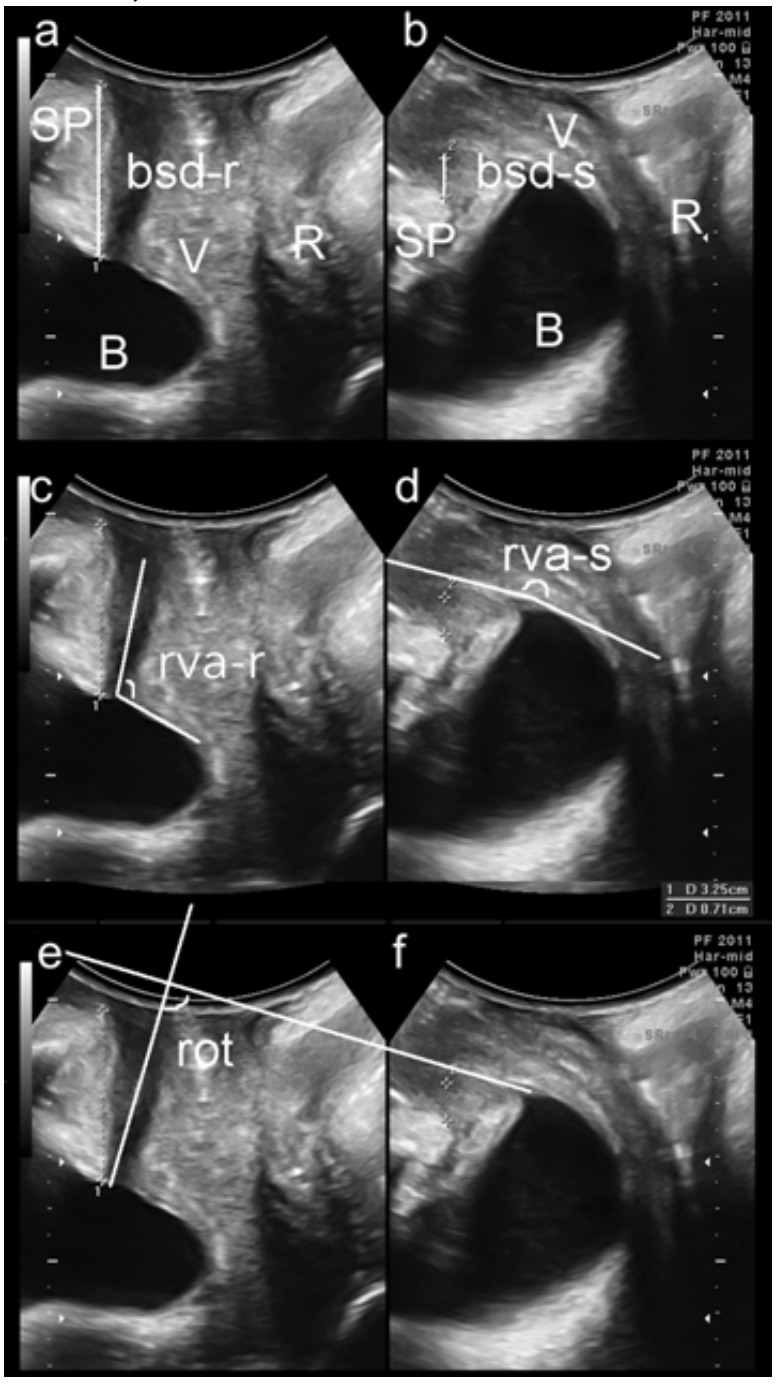
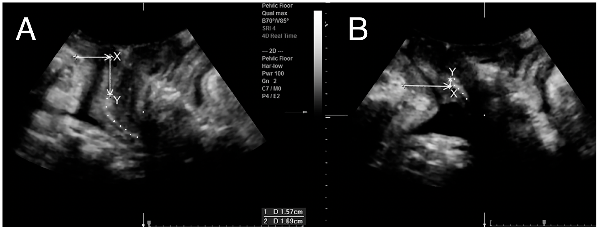
- Split screen: images at rest (left) and on maximal Valsalva >= 6s, (right).
- Used to measure bladder neck and bladder descent (a,b), retrovesical angle (c,d) urethral rotation (e,f), (Fig 2).
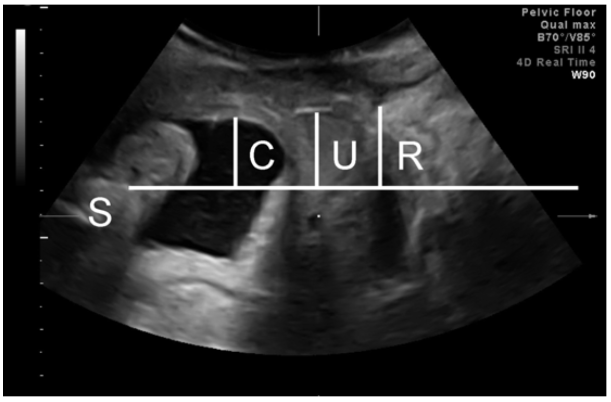
- Single screen: image on maximal Valsalva to determine organ descent (Fig 3). Let the prolapse come- no pressure on perineum, without tilting the hand!
- Check for hyperechogenic structures (slings and meshes) in anterior and posterior vaginal wall.
- Check for cystic structures (urethral diverticula, Gartner cysts, nabothian follicles, ureterocele.
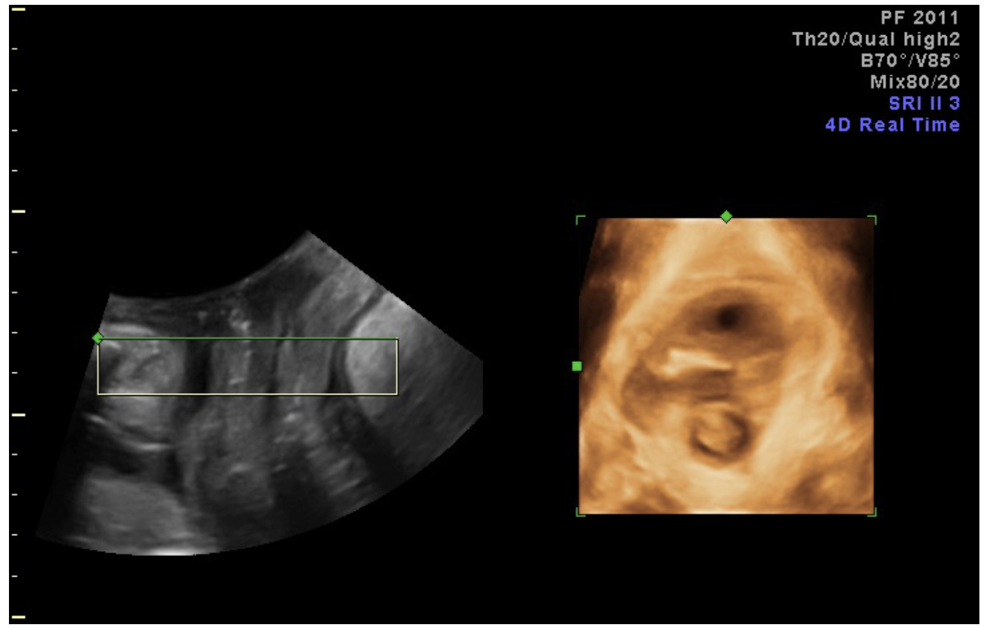
2.) 4D acquisition for prolapse/ hiatal area assessment
- Set acquisition angle at 85 degrees (or system maximum)
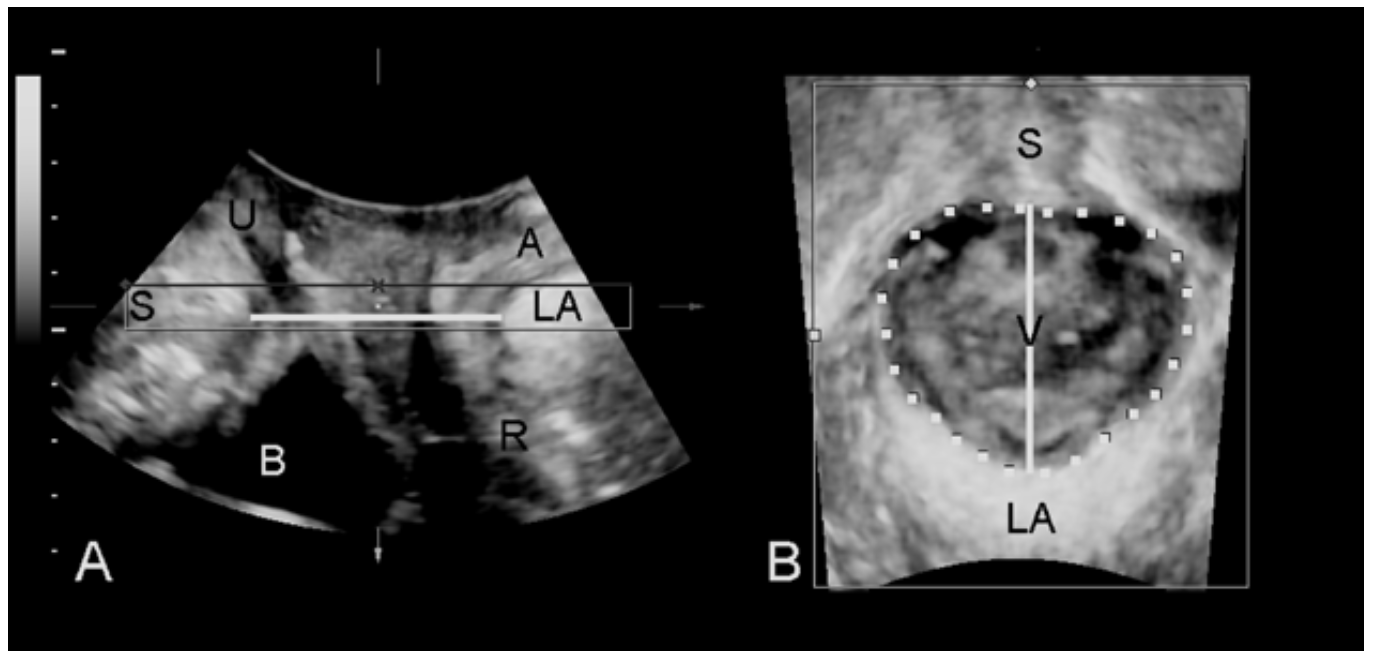
- 2 split screen with rendered volume on right, set the region of interest (the box shown in A) to 0.5-2 cm thickness, green line at top, place the box to include the plane of minimal hiatal dimensions (Fig 4). One may need to rotate the image so that the plane of minimal hiatal dimensions lies within the box, as in Fig 4.
- Keep right-hand image symmetrical and in the centre throughout acquisition, and keep SP in left- hand image. No pressure on transducer. Avoid levator co-activation (Fig. 5). Biofeedback teaching if there is levator coactivation. Valsalva >= 6 s.
- Measure hiatal area on rendered volume (right). Move the Box (area of interest) in A for clear image of the hiatus for measurement. Use whatever thickness (0.5-2 cm) gives you the best contour. Check distance of hiatal contour from image edge in A and B.

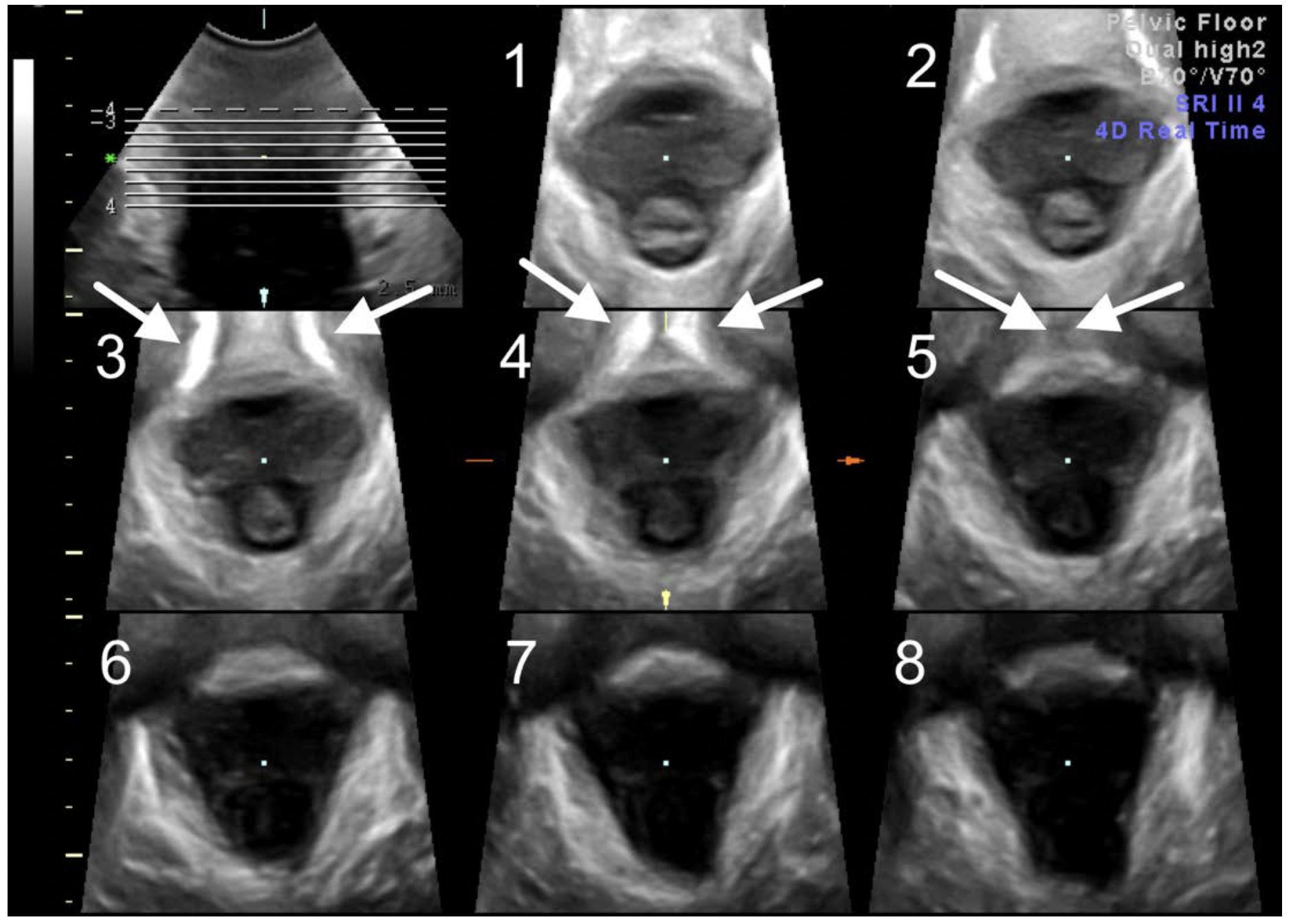
3.) PFMC for tomographic imaging of levator integrity:
- Views as above- make sure symphysis is visible.
- Ask for PFMC, and make sure the levator ani muscle remains visible. May need pressure on the perineum.
- Rotate the A plane to place plane of minimal dimensions (minimal distance from SP to LA) in middle of box (Figure 6).
- Switch to TUI (tomographic ultrasound imaging) in the C (axial) plane and rotate this plane so that the image is upright. Set the interslice interval at 2.5 mm, 8 slices (see Figure 7).
- May need further adjustment so that the SP in the 3 central slices (i.e.slice 3 to 5 in Fig 7) appear open (slice 3), closing (slice 4) and closed (slice 5) (Figure 7).
- Rate central three slices for integrity of the insertion of the puborectalis muscle.
- When in doubt measure levator-urethral gap between centre of the urethra and PR insertion (Figure 8). Limit of normal in Caucasians is 2.5 cm.

4.) 4D Acquisition for imaging of the anal canal
- Place transducer transversely over introitus after reducing aperture to 60 degrees. Apply additional gel centrally. Tilt the probe towards the canal (see Figure 9 A) so as to obtain a transverse view of the anal canal (see Figure 9 B)
- SRI 3-4, CRI 2-4, high harmonics, +/- VCI
- Set acquisition angle at 70 degrees to image the whole length of the anal canal.
- One focal zone as close as possible to the probe surface.
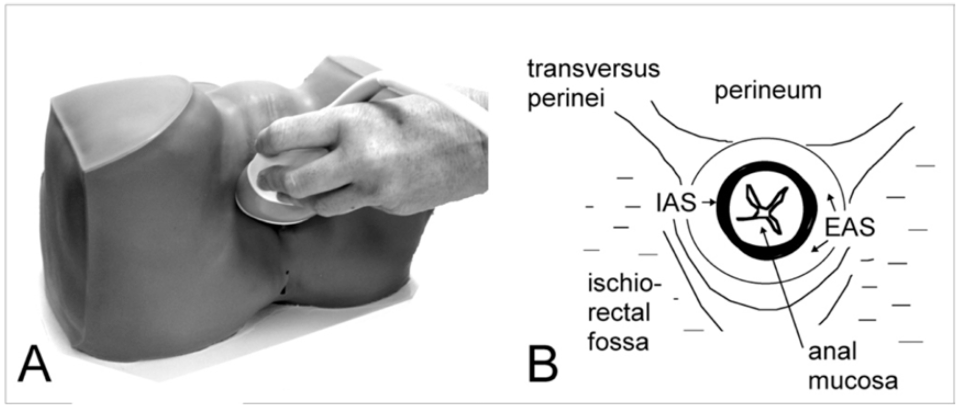
- view transverse plane as A, midsagittal plane as B, and identify the fascial plane separating the EAS from the levator ani in the B plane (Figure 10). If the B plane shows horizontal parallel dark stripes and if those parallel dark stripes, ie., the internal sphincter, are vertical in the C plane, then the image is properly centred.
- ask patient to perform PFMC, take care the entire EAS is within the field of vision.
- Adjust transducer pressure to stay close without deforming the ring shape of the sphincter.
- Select A plane and TUI. Adjust interslice interval to include the entire EAS (see Figure 11).
- Measure defects by determining defect angle (Figure 12) in slices 2-7.


5.) Imaging of implants
Ultrasound imaging of implants may be required in women with sling complications such as recurrent stress incontinence, voiding dysfunction, recurrent UTIs or pain, in order to assess type, location and function. Imaging of meshes may be needed in women with recurrence, pain and if there is a suspicion of perforation into the bladder or rectum. Vaginal erosion does not seem to produce unequivocal sonographic signs.
Slings
The aim of the imaging is to describe both location and function. Therefore imaging
at rest and dynamic assessment during a Valsalva maneuver is needed.
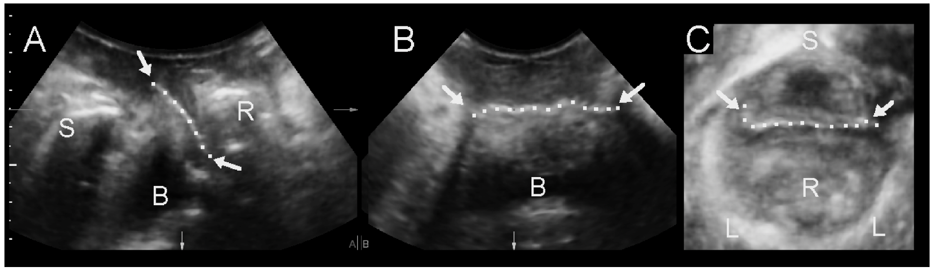
In the midsagittal plane polypropylene implants are visible as hyperechogenic
structures (Fig. 13) posterior to the urethra, although occasionally one may
be found at the bladder neck. In the coronal or B plane such implants should
be visible as a strip- like line, likewise for the axial plane. There may be
asymmetrical misplacement of the implant which may be termed ‘tethering’,
which is not always associated with symptoms. One should be careful with a
diagnosis of ‘perforation’ which needs to be confirmed by cysto-urethroscopy.
Mid- urethral slings such as the TVT, TOT, Monarc, Sparc etc. tend to become
more visible on Valsalva as they often rotate into a more horizontal position.
Assessment on Vaslalva is essential as this improves visibility due to changing
intonation angle, and to assess dynamic compression of the urethra. While 2D
imaging provides much of the information needed, 4D imaging in the orthogonal
planes, or as rendered volumes, is often helpful. Tomographic imaging
may occasionally be useful.
Minislings tend to look like standard MUS and can be diffcult to distinguish.
The IVS, an older sling used between 1995 and 2005, is much harder to identify
and often only visible in the axial plane. The TFS (Tissue Fixation system)
and more recently developed MUS such as the Advantage sling seem more
hyperechogenic and tend to curl less, suggesting higher stiffness.
Describe
- Location of sling at rest and on Valsalva relative to the external and internal urethral meatus, especially if surgical removal may be contemplated. (Fig. 13)
- Location of sling relative to urethral structures: between vaginal muscularis and rhabdosphincter, within the rhabdosphincter, within the longitudinal smooth muscle, on the ventral side of the urethra, in the space of Retzius, ‘tethering’ (Fig.13)
- Sling shape: linear, curved, C or U shape
- Type: retropubic or transobturator (Fig. 14)
- Determine the Sling- pubis gap as a measure of urethral compression.( Fig. 13).


Meshes
As with slings the aim is to assess location and function. In the midsagittal
plane, anterior and posterior compartment prolapse meshes such as Prolift,
Apogee/ Perigee, Ant/ Post. Elevate, Uphold etc. can readily be observed
as linear hyperechogenic structures (Figure 15), while sacrocolpopexy
meshes are often too cranial to be obvious. However, in some cases they
may be seen close to the trigone.
Anterior compartment meshes usually are visible as flat lines, but
sometimes seem folded, especially older meshes. The Anterior Prolift
was particularly large, hence it often appears folded (see Figure 15).
Such meshes are sometimes difficult to visualize in detail. It is suggested
that mesh appearances are described together with its location relative
to the internal urethral meatus.
Posterior meshes are visible as linear structures anterior to the rectal
ampulla. Recurrence posterior to such a mesh may be evident as a true
rectocele, an enterocele or an intussusception. A recurrence anterior to the
mesh occurs as enterocele. It is suggested that posterior compartment
mesh is described by its appearance and location relative to the introitus.
For mesh location, especially for more cranially placed meshes,
intravaginal ultrasound may also be used. However, functional asssement
requires the perineal/ trans-labial approach.
Describe
- Type: Anterior: Transobturator mesh or apically anchored mesh (Fig. 15), Sacrocolpopexy mesh (Fig. 16); posterior mesh.
- Location of mesh at rest relative to symphysis pubis and the internal urethral meatus at rest and on Valsalva, especially if surgical removal may be contemplated.
- Location of mesh relative to other structures: bladder, cervix, rectum
- Shape: linear or folded, at rest and on Valsalva
- Extent: in midsagittal and coronal/ axial planes.(Fig. 17)
- Behaviour on Valsalva: anterior, apical or global anchoring or support failure. (Fig 18)


Further reading:
Dietz HP. Pelvic Floor Ultrasound. In: Rizk and Puschek, Ultrasonography in
Gynecology. Cambridge University Press 2013
Dietz HP. Ultrasonography. In: Evidence based physiotherapy for the pelvic
floor: bridging research and clinical practice. 2nd Edition. K. Bo, B.
Berghmans, M. van Kampen and S Morkved Eds. Butterworth Heinemann
Elsevier, 2014
Shek KL, Dietz HP. Imaging of slings and meshes. Australasian Journal of
Ultrasound in Medicine May 2014; 17 (2): 61-71
Dietz HP. Pelvic Floor Ultrasound. In: Sonography in Obstetrics and
Gynecology: Principles and Practice. 8th ed. Fleischer AC et al., Mc Graw Hill
2016
Dietz HP. Pelvic Floor Ultrasound: Normal Anatomy. In: Merz E. Atlas of 3D/
4D Ultrasound in Obstetrics and Gynecology. Thieme Stuttgart, 2016.
Dietz HP. Pelvic Floor Ultrasound: Abnormal findings. In: Merz E. Atlas of 3D/
4D Ultrasound in Obstetrics and Gynecology. Thieme Stuttgart, 2016.
Shek KL, Dietz HP. Assessment of Pelvic Organ Prolapse: A Review -
Ultrasound Obstet Gynecol Gynecol 2016; 48: 681-692 DOI: 10.1002/uog.
15881